:ontiition
B
Continued)
ondition
C
'nplug sprayed
ed
lamp
on,
clear lamp
oi
WHAT
TO
CHECK
If
check
is
OK,
go
to
next
check
6.
Check motor thermal cutout switch.
female. Plug in and turn
on
sprayer. Meter
Connect volt meter to TP6 female and
TP9
should read
105
to
125
VAC. Turn
off
and
unplug sprayer.
7.
Check microswitch
1301).
Reconnect
TP6
connectors. Connect volt meter to TP15
VAC.
male and TP4. Meter should read
50-125
8.
Visually inspect microswitch
1301)
button.
Adjustment stud
101
should
not
depress th
microswitch bunon when fluid pressure is
with small screwdriver; an audible click in-
zero.
Manually check by depressing button
dicates.micmswitch
is
in
normal position.
9.
Check microswitch
1301)
continuity with
oh
meter. Be
sure
sprayer
is
unplugged1
Mete!
should read zero ohms with
no
fluid pressu
in the sprayer.
10.Check
all
terminals for damage or
loose
fit.
Reconnect
Tffi
connectors.
11.Check circuit board
l307)
by substituting
w'kh
a
good board.
See
page
22.
I.
Check circuit board
1121)
by removing from
box
without
disconnecting wires;
see
page
22
for removal procedure.
-
WARNING:
Removing the circuit board
while
Su'll
wired over-rides the optical detec
tor which could
causa
the sprayer to ovar-
tion
properly. Turn the sprayer
on
ONLY
pressurize.
if
the microswitch does
not
func
long enough to check lamp condition, then
WARMING:
To reduce
the
risk of electric
shut
off
immediately.
shock, handle board by edges onbl
Do
not
with the board1
allow any metal objects to come in contact
Plug in and turn
on
sprayer. Clear lamp
should be
on
now
-
removing the circuit
off
and unplug sprayer.
board over-rides the optical detector.
Turn
.
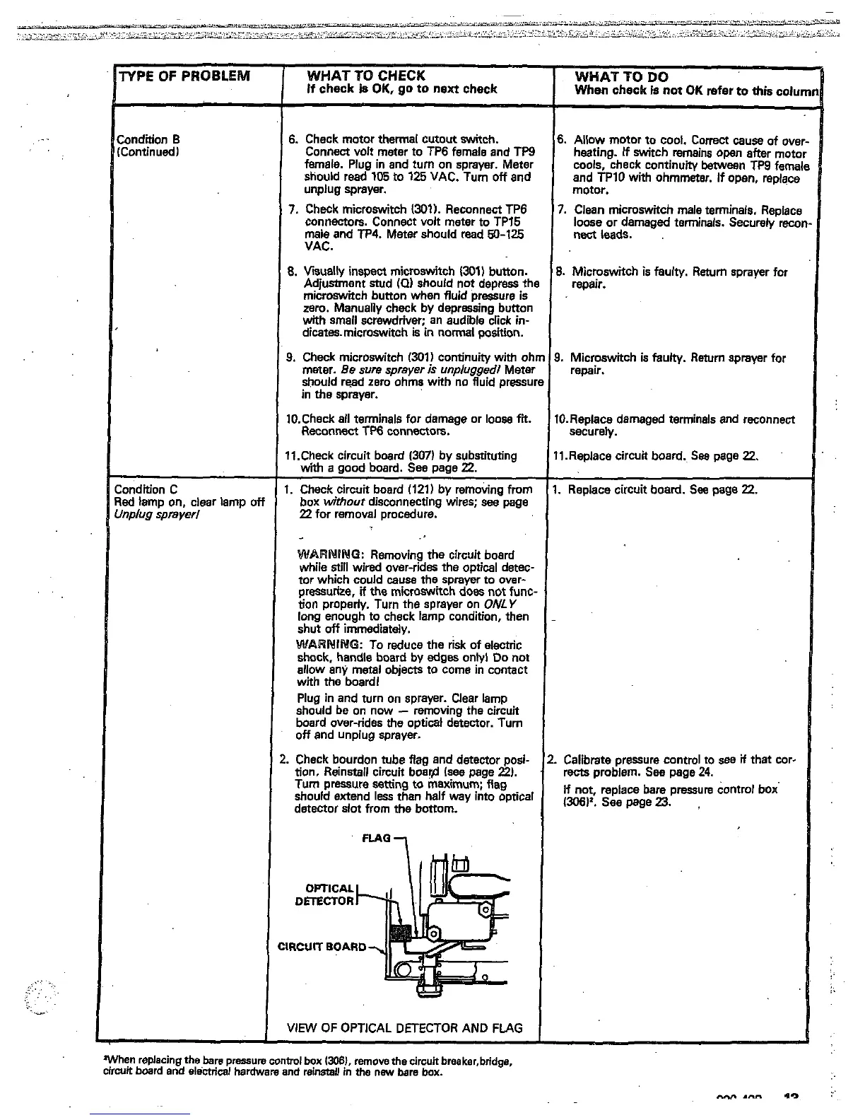
Check bourdon tube flag and detector posi-
tion. Reinstall circuit boar@ (see page
2).
Tum pressure
setting
to maximum; flag
detector slot from
the bottom.
should extend
less
than half way into optical
DmCTOR
OPTICAL
IRCUIT
BOARD
VIEW
OF
OPTICAL DETECTOR AND
FLAG
When replacing
the
bare
pressure
control
box
13081.
remove
the
cirwtt
breaker,bridge.
circuit board and
electrical
hardware
and
reinstall
in
the
new
bare
box.
When
check
is
not
OK
refer
to
thk
colu
WHAT
TO
DO
6.
Allow
motor
to cool. Correct
cause
of ove
heating.
If
switch remains
open
after
motc
cools, check continuity
Ween
TW
fama
and
TPlO
with ohmmeter.
if
open, replacs
motor.
7.
Clean microswitch male terminals. Raolact
nect
leads.
loose or damaged terminals. Securely
rex
~~~-
~~
8.
Microswitch
is
faulty. Return sprayer for
repair.
3.
Microswitch
is
faulty.
Return
sprayer for
remir.
I0.Replace damaged terminals and reconnect
I1.Replace circuit board.
See
page
22.
securely.
.
Replace circuit board.
See
page
22.
Calibrate pressure contml to
see
if
that cor-
rects
problem.
See
page
24.
(306)'.
see
page
23.
If not, replace bare pressure control box
 Loading...