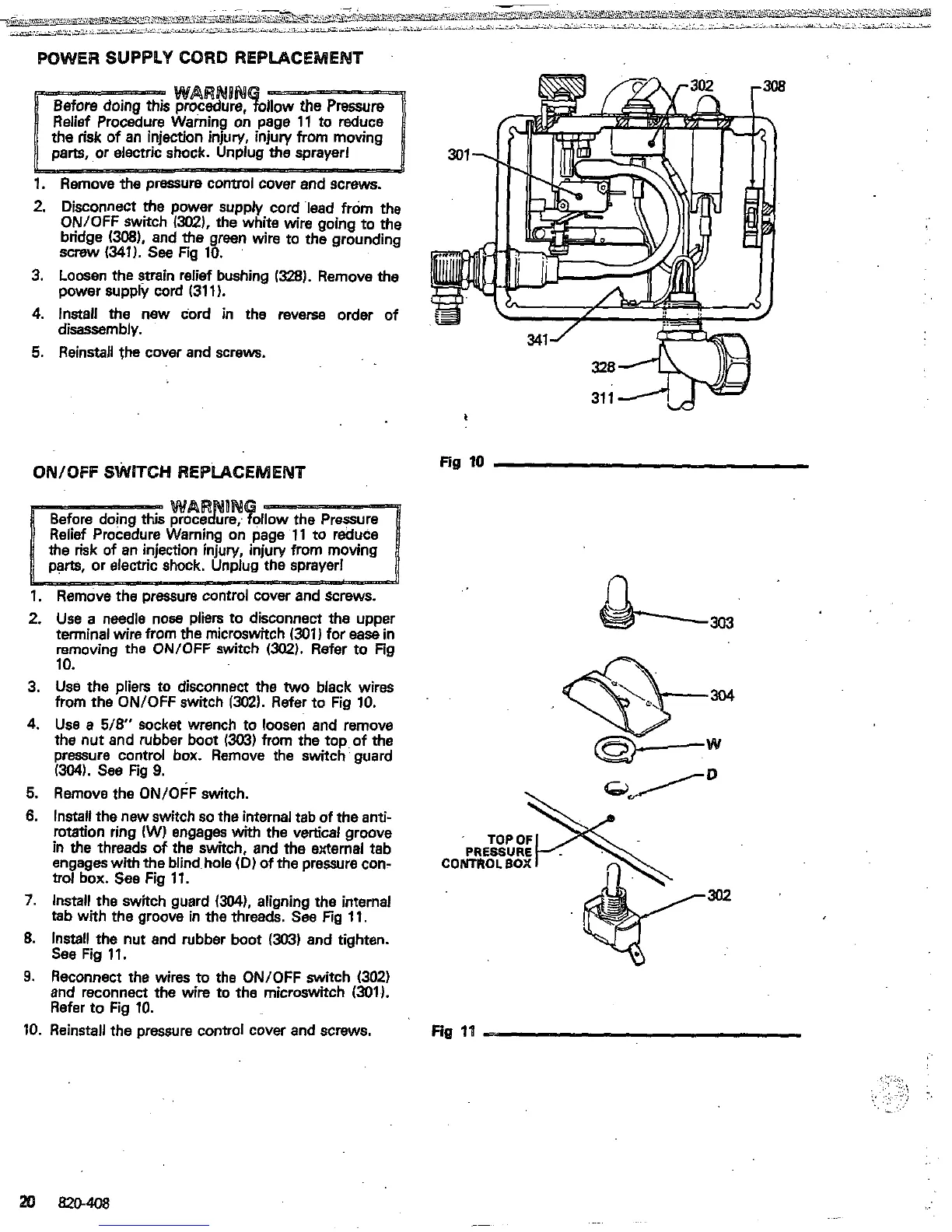
POWER SUPPLY CORD REPLACEMENT
1.
Remove the pressure control cover and screws.
2.
Disconnect
the
power supply cord lead from the
ON/OFF switch
/XU).
the white
wire
ooino
to
the
bridge
(W),
and the.green
wire
to~the
grounding
"
screw
(341).
see
Fig
10.
3.
Loosen the strain relief bushing
1328).
Remove
the
4.
Install the new cord in the reverse order of
5.
Reinstall the cover
and
screws.
power supply cord
(311).
disassembly.
QNIQFF
SWITCH REPLACEMENT
Fig
10
1.
Remove
the
Dressure control cover and screws.
n
2.
3.
4.
5.
6.
7.
8.
9.
10.
Use
a needle nose pliers to disconnect the upper
terminal wire from
the
microswitch
(301)
for
ease
in
removing the ONlOFF switch
~302).
Refer to Fig
10.
from
the
ON/OFF switch
1302).
Refer to Fig
10.
Use
the pliers to disconnect the
two
black wires
the nut and rubber boot
13G3)
from the toD of
the
Use
a
5/8"
socket wrench to loosen
and
remove
pressure control box. Remove the switch
'
guard
(3041.
See Fig
9.
Remove the ON/OFF switch.
Install the new switch
so
the internal tab
of
the
anti-
in
the
threads
of
the switch, and the external tab
rotation ring
(W)
engages with the vertical groove
engages with
the
blind hole
(D)
of
the pressure con-
CONTROL
BOX
trot box.
See
Fig
11.
Install the switch guard
(304).
aligning the internal
302
tab
with the groove in the threads.
See
Fig
11.
Install the nut and rubber boot
(303)
and tighten.
See
Fig
11.
and reconnect the wire to the microswitch
(301).
Reconnect the wires to the ON/OFF switch
(302)
Refer to Fig
10.
Reinstall the pressure control cover and screws. Fig
1'1
-.
:.
..
ij
...,.
.
,...
:.:.:
.
,
.
. .
.
..
.:
'
..
.:
 Loading...