NOTE:
New. motor brushes
are
included with each
brushes when replacing the packings,
Packing Repair
Kit
No.
820041.
Replace the
..
and/or when
the
brushes have been worn to
a
minimum of
9/16
on the longest side.
!
.
.-
I
I
I
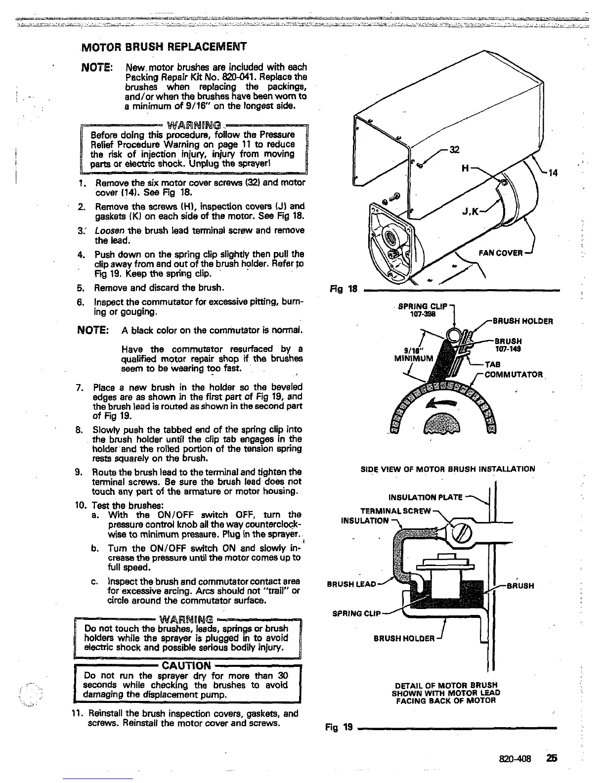
1.
Remove the
six
motor cover screws
(321
and
motor
cover
(141.
See
Fig
18.
2.
Remove the
screws
(H),
inspection covers
(J)
and
gaskets
iK1
on each side
of
the motor.
See
Fig
18.
3:
Loosen
the
brush lead terminal screw and remove
the lead.
4.
Push down on the spring clip slightly then pull the
clip away from and
out
of the brush holder. Refer
fo
Fw
19.
Keep the spring clip.
5.
Remove and discard the brush.
6.
Inspect the commutator for excessive pitting, burn-
ing or gouging.
NOTE:
A
black color on the commutator is normal.
qualified motor repair shop
if
the
brushes
Have
the
commutator resurfaced by
a
seem to be wearing
too
fast.
'.
7.
Place
a
new brush in the holder
so
the beveled
edges are as shown in the
first
part
of
Fig
19,
and
the brush lead
is
routed as shown in the second part
8.
Slowly push the tabbed end of the spring clip into
the brush holder until the clip tab engages
in
the
holdwand the rolled portion
of
the tension spring
rests squarely
on
the brush.
9.
Route the brush lead to the terminal and tighten the
terminal screws.
Be
sure
the
brush lead
does
not
touch any pert
of
the armature or motor housing.
of Fig
19.
10.
Test
the brushes:
a.
With
the
ON/OFF switch OFF, turn the
wise
to
minimum pressure.
Plug
in
the
sprayer.
pressure control knob
all
the way counterclock-
b. Turn the ON/OFF switch ON and slowly in-
full speed.
crease the pressure
until
the motor comes up to
c. Inspect the brush and commutator contact area
for excessive arcing.
Arcs
should
not
"trail" or
circle around the commutator surface.
CAUTION
Do
not run the sprayer dn/ for more than
30
seconds while checking the brushes
to
avoid
damaging the displacement pump.
..
.
..
~..
..
. .
..
.
.....,
17.
Reinstall the brush inspection covers, gaskets, and
screws. Reinstall the motor cover and screws.
a
:..
....
fin
SPMNICLIP
1
rBRUSH HOLDER
TOR
SIDE,
VIEW
OF MCTOR BRUSH INSTALLATION
INSULATION PIATE
TERMINALSCREW
BRUSH
LEAD
SPRING CLIP
DETAIL
OF
MOTOR
BRUSH
SHOWN
WITH
MOTOR
LEAD
FACING BACK
OF
MOTOR
Fig
19
820-408
25
 Loading...