Do you have a question about the Shield Omega-X and is the answer not in the manual?
Provides instructions for installing, testing, and troubleshooting the Omega-X panel.
Lists other documents providing additional information for installing the Omega-X Panel.
Explains conventions for part numbers and writing styles used in the manual.
Provides contact information for technical support and details on warranty and repair policies.
Outlines policies for out-of-warranty items, customer repairs, repair warranties, and returning items for credit.
Explains points and addresses for device identification and configuration on the Omega-X Panel.
Details address limitations for Contact ID format communication with monitoring centers.
Describes the internal components of the Omega-X Panel, including power supply, control board, and batteries.
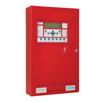
Details the LCD display, control pads, and indicator lights on the Omega-X front panel.
Describes the upper-panel control-pad buttons and their functions for navigation and operation.
Details the lower-panel control-pad buttons and their functions for alarm silencing, reset, and fire drill.
The Shield Omega-X Panel is a sophisticated fire alarm control panel designed for comprehensive fire detection and reporting. It operates using the Apollo protocol for its Signaling Line Circuits (SLC) devices and is available in both 2-loop and 4-loop models. The 2-loop models include the No Communication SA-P20 and the Network Interface Card (Omega-N) SA-P2E, while the 4-loop models offer the No Communication with Loop Expansion SA-P4L and the Network Interface Card (Omega-N) with Loop Expansion SA-P4E. These panels are capable of accepting a variety of industry-standard devices for Fire Alarm Control Panel (FACP) monitoring and reporting. They can also be linked with other panels using the proprietary Omega-N to monitor conditions between panels and provide reports to monitoring centers via a standard TELCO line.
The Omega-X Panel serves as a local signaling unit and supports releasing functions for Omega-X Panels only (non-releasing for other Omega-X Panels). It handles automatic fire alarms, manual fire alarms, waterflow alarms, and sprinkler supervisory services. The panel supports Style 4, 6, or 7 for Signaling Line Circuits and Style Y for Notification Appliance Circuits. It features non-coded signaling and includes an integrated dialer for DACT (Digital Alarm Communicator Transmitter) functionality. The panel can be configured for Remote Station (RS) Protected Premises Unit (PPU) Omega-N communication, Central Station (CS) Protected Premises Unit (PPU) Omega-N communication, and Proprietary (P) Protected Premises Unit (PPU) with releasing, non-releasing, and Omega-N communication. These communication options are available for models SA-P20XX, SA-P2EXX, SA-P4LXX, and SA-P4EXX, each with a Modem DACT SA-DACT.
The Omega-X Panel supports a maximum of 126 points per loop without subpoints or 381 points per loop when utilizing subpoints. The total addressable capacity for the panel is 800 addresses (points and subpoints). When using the Contact ID digital communication format for monitoring-center communication, there are address restrictions. Analog-sounder-bases should not be assigned using the Contact ID format, as its address range is insufficient for reporting their status. The Contact ID format limits reporting to an address of 99. While the eSP Discovery application restricts the use of Contact ID for addresses above 99, it can be used for other devices as long as their address and sub-address are below 99. For situations where the 99-address limit per loop cannot be avoided, FACP reporting can be switched from point reporting to zone reporting, though this reduces overall reporting granularity. The panel can be programmed for either SIA or Contact ID digital communication formats, both providing status monitoring and reporting to industry-standard receivers. The eSP Discovery application uses an open protocol for assigning device addresses.
The panel's internal components include a Modem-DACT, a Control Unit Board, a 4 Amp OEM 1 Power Supply, a Panel Annunciator Board, and Batteries.
The front panel of the Omega-X features an LCD display, upper-control-pad, lower-control-pad, left-panel-indicators, and right-panel-indicators.
Certain programming features must be limited for UL 864 9th Edition compliance:
The manual provides instructions for routine service and repair, including inspecting and replacing standby batteries, and replacing fuses (10 Amp Battery Fuse and 3 Amp Power-Supply Fuse). It also covers replacing internal and cabinet components. For technical support, Shield Fire, Safety and Security Ltd. can be contacted via phone or email. The company offers a limited returns and repairs policy, including in-warranty items, damaged goods, and component failure. Service Replacement Items (SRI) are available for replacement parts under warranty, provided certain conditions are met regarding return of faulty parts and packaging. Out-of-warranty items can be tested and repaired, subject to component availability and customer authorization. Items returned for credit are accepted within the first 3 months of supply, requiring an RMA reference number and adherence to specific return procedures.
Installation must comply with NFPA 13, NFPA 72, NEC 70, and all local codes.
The manual also includes appendices for specifications (electrical, SLC ratings, programmable relay contact ratings, power output circuits, unsupervised inputs, RS485 serial bus, auxiliary 24 VDC, Omega-N terminals, 4 Amp OEM 1 power supply, AC line connection, cabling, operating environment, physical specifications), an equipment list (Shield Omega-X Panels, loop devices, accessories, replacement parts, compatible notification appliance circuits, authorized special application devices, compatible devices for auxiliary 24V), current draw calculations, a door label copy, and operating instructions.
| Brand | Shield |
|---|---|
| Model | Omega-X |
| Category | Firefighting Equipment |
| Language | English |