EasyManua.ls Logo

Shimano ST-5510 User Manual

Shimano ST-5510
9 pages
To Next Page IconTo Next Page
Page #1 background imageLoading...
Page #1 background image
Technical Service Instructions SI-6C80D
ST-6510
ST-5500-CA
ST-5510
ST-R600
Shimano
Total Integration
General Safety Information
WARNING
Obtain, read and carefully service instructions when installing
parts. A loose, worn, or damaged parts may cause injury to
the rider.
We strongly recommend that only genuine Shimano
replacement parts be used.
Read these Technical Service Instructions carefully, and keep
them in a safe place for later reference.
Note
Operation of the levers related to gear shifting should be made
only when the front chainwheel is turning.
For smooth operation, always be sure to use the specified
outer casing and the bottom bracket cable guide.
Grease the inner cable and the inside of the outer casing
before use to ensure that they slide properly.
Because the high cable resistance of a frame with internal
cable routing would impair the SIS function, this type of frame
should not be used.
The end of the outer casing which has the aluminum
cap should be at the derailleur side.
Derailleur side
4-mm cap
Plastic cap or 4-mm capAluminum cap
The cycle computers shown in the table below are compatible.
Read the service instructions for the cycle computer also.
Parts are not guaranteed against natural wear or deterioration
resulting from normal use.
For maximum performance we highly recommend Shimano
lubricants and maintenance products.
For any questions regarding methods of installation,
adjustment, maintenance or operation, please contact a
professional bicycle dealer.
SM-6500
*1
/ SM-6500-RS / SM-6501
SC-6500 / SC-6501 / SC-M500
Meter unit
Bracket sensor unit
*1
The bracket cover must be replaced.
()
ST-6510 ---> Replace with bracket cover for ST-6501.
ST-5500-CA ---> Replace with ST-5500-C.
27
FD-6503
FC-6503
RD-6500-GS
Series
Shifting lever
Outer casing
Gears
Front derailleur
Front chainwheel
Bottom bracket
Rear derailleur
Freehub
Cassette sprocket
Chain
ULTEGRA
ST-6510 / ST-R600
18
SP40
FH-6500
CS-6500
CN-HG93 / CN-7701
FD-6500
FC-6500
BB-6500
RD-6500
Bottom bracket cable guide
SM-SP17
In order to realize the best performance, we recommend that
the following combination be used.
27
FD-5503 / FD-5504
FC-5504 / FC-5505
RD-5500-GS /
RD-5501-GS
Series
Shifting lever
Outer casing
Gears
Front derailleur
Front chainwheel
Bottom bracket
Rear derailleur
Freehub
Cassette sprocket
Chain
SHIMANO 105
ST-5500-CA / ST-5510 / ST-R600
18
SP40
FH-5500 / FH-5501
CS-HG70-9
CN-HG73
FD-5500 / FD-5501
FC-5501 / FC-5502
BB-5500
RD-5500 /
RD-5501
Bottom bracket cable guide
SM-SP17
t
Question and Answer IconNeed help?

Do you have a question about the Shimano ST-5510 and is the answer not in the manual?

Shimano ST-5510 Specifications

General IconGeneral
BrandShimano
ModelST-5510
CategoryBicycle Accessories
LanguageEnglish

Summary

General Safety Information

Recommended Component Combinations

Lists compatible parts for ULTEGRA and SHIMANO 105 series for optimal performance.

Operation

Rear Derailleur Lever Operation

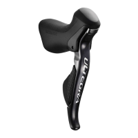
Explains operation of rear derailleur levers A and B with click stops for shifting sprockets.

Front Derailleur Lever Operation

Details front derailleur lever A and B operations for specific models, including trimming and noise prevention.

Operation Cautions

Advises against simultaneous lever pressure and recommends reading other service instructions.

Installation

Handlebar Installation

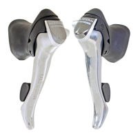
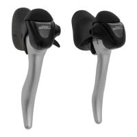
Describes securing the shifting lever assembly to the handlebar using an installation nut.

Brake Cable Installation

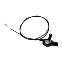
Guides on routing and securing the brake cable through the lever and outer casing.

Shifting Cable Installation

Details inserting and cutting the inner and outer casings for the shifting cable.

Outer Stopper Installation

Explains how to install the outer stopper on the down tube for the rear chainwheels.

Maintenance

Bracket and Lever Disassembly

Step-by-step guide to disassembling the bracket and lever assembly, including sensor cable removal.

Lever and Bearing Assembly Disassembly

Procedure for disassembling the lever and bearing assembly using special tools.

Bracket and Lever Reassembly

Instructions for reassembling the bracket and lever components, including spring and sensor cable.

Bracket Cover Replacement

Guide on how to replace the bracket cover, noting left and right side markings.

Related product manuals