Installation
■ Wheel spoke lacing
Check that the spokes have been laced as shown in the illustration.
A radial assembly cannot be used.
Lace the spokes as shown in Figure 1 below for the left side of the front wheel
(the side where the rotor is installed), and the left and right sides of the rear
wheel, and as shown in Figure 2 below for the right side of the front wheel.
■ Installation of the rotor
<SM-RT61>
Install the rotor and the rotor tightening plate to the hub, and then install and
tighten the bolts as shown in Fig. 1.
<SM-RT62>
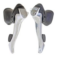
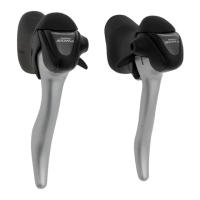
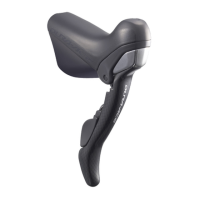
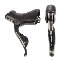
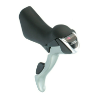
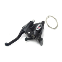
■ Installation of the brake lever
Use a 5 mm Allen key to install.
■ Installing the calipers
While wearing gloves, apply a force to the
rotor to turn it in a clockwise direction as
shown in Fig. 2. While doing this, tighten
the rotor fixing bolts in the order shown in
the illustration.
Use a flat-tipped screwdriver or similar tool to bend the edges of the tightening
plate over the heads of the bolts as shown in Fig. 3.
Rotating
direction of
wheel
Front left Rear left Rear right Front right
Fig. 1 Fig. 2
Fig. 1
Tightening plate
Rotor
Hub
Rotor fixing bolts (#T25 torx)
Tightening torque:
2 - 4 N·m {18 - 35 in. lbs.}
Fig. 2 Fig. 3
Tightening plate
Use a handlebar grip with a maximum
outer diameter of 32 mm.
Tightening torque:
6 - 8 N·m {53 - 69 in. lbs.}
1. Install the bicycle wheel. Loosen the
caliper fixing bolts, and then install
the calipers to the frame so that the
calipers work at the left and right.
Caliper clamp bolt
Caliper fixing bolts
2. While wearing protective gloves, apply pressure to the adapter in the
counterclockwise direction while tightening the caliper clamp bolt.
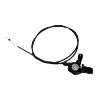
3. Securing the cable
Place the inner cable as shown in
the illustration, and then tighten
the cable fixing bolt.
6. Depress the brake lever about
10 times until it touches the grip,
and check that there are no
problems with any components,
and also that the rotors and the
pads do not interfere with each
other when the wheel is rotated.
7. Turn the cable adjusting bolt to take up any slack in the cable.
Caliper clamp bolt
Adapter
Tightening torque:
6 - 8 N·m {53 - 69 in. lbs.}
Tightening torque:
6 - 8 N·m {53 - 69 in. lbs.}
4. While depressing the brake lever, set the calipers to the required position and
then tighten the caliper fixing bolts.
Tightening torque:
6 - 8 N·m {53 - 69 in. lbs.}
5. Loosen the pad adjustment screw by
two clicks.
Cable fixing bolt
Inner cable
Depress
about
10 times
Secure the three bolts with a cap as shown in the illustration in order to
prevent the bolts from coming loose.
Caps
< Front > < Rear >
■ For post type
Caps
■ Adjusting when the pads are worn
Use a 3 mm Allen key to tighten the pad adjustment screw on the calipers so that
clearances (A) and (B) are both 0.2 – 0.4 mm.
If the brake pads are worn down to a thickness of 0.5 mm, replace the brake pads.
Replacing the brake pads
1. Remove the bicycle wheel from the frame, and then remove the brake pads as
shown in the illustration.
2. Loosen the pad adjusting screw
and turn the cable adjusting bolts at
the brake lever clockwise to loosen
them.
Pads
Rotor
Cable adjusting bolt
Caliper
Brake Lever
Rotor
Brake cable
BR-M545
ST-M410
SM-RT61, SM-RT62
Brake pad unit (Metal Pads)
M06
General Safety Information
WARNING
• Please use extra caution to keep your fingers away from the rotating
disc brake rotor during installing or servicing the wheel. The rotor is
sharp enough to inflict severe injury to your fingers if caught within the
openings of moving rotor.
• Adjust the inner cable so that the protruding length is less than 20 mm
(3/4 inch). If the protruding length is any longer, the end of the inner
cable may become stuck in the rotor, which could cause the wheel to
lock and the bicycle could fall forward causing serious injuries.
• The calipers and rotor will become hot when the brakes are operated,
so do not touch them while riding or immediately after dismounting
from the bicycle, otherwise you may get burned. Check that the brake
components have cooled down sufficiently before attempting to adjust
the brakes.
• Always make sure that the front and rear brakes are working correctly
before you ride the bicycle.
• Before riding the bicycle, check that the pad thicknesses are 0.5 mm or
more.
• Be careful not to allow any oil or grease to get onto the rotor and brake
pads, otherwise the brakes may not work correctly.
• If any oil or grease do get on the pads, you should replace the pads. If
any oil or grease gets on the rotor, you should clean the rotor. If this is not done, the
brakes may not work correctly.
• Check the brake cable for rust and fraying, and replace the cable immediately if any such
problems are found. If this is not done, the brakes may not work correctly.
• The required braking distance will be longer during wet weather.
Reduce your speed and apply the brakes early and gently.
• If the road surface is wet, the tires will skid more easily. If the tires skid, you may fall off
the bicycle. To avoid this, reduce your speed and apply the brakes early and gently.
• Check that the quick release lever is on the right side (the opposite side to the rotor). If
the quick release lever is on the same side as the rotor, there is the danger that it may
interfere with the rotor, so check that it does not interfere.
• It is important to completely understand the operation of your bicycle's brake system.
Improper use of your bicycle's brake system may result in a loss of control or an
accident, which could lead to severe injury. Because each bicycle may handle differently,
be sure to learn the proper braking technique (including brake lever pressure and bicycle
control characteristics) and operation of your bicycle. This can be done by consulting
your professional bicycle dealer and the bicycle's owners manual, and by practicing your
riding and braking technique.
• The
M545
disc brakes are designed for optimum performance when used in combination
with the BR-
M545
(calipers), ST-M410 (brake lever), SM-RT61, SM-RT62 (rotor) and
Shimano pad unit (M06). The brake lever used should be a two-finger lever for V-brakes,
such as the ST-M410.
If using in combination with 4-finger levers such as the BL-T400/ST-T400, the braking
force will be higher. Accordingly, under some conditions such as certain riding positions
or overall weight, the bicycle may fall over and injury may result if proper care is not
taken.
• Obtain and read the service instructions carefully prior to installing the parts. Loose,
worn, or damaged parts may cause injury to the rider.
We strongly recommend only using genuine Shimano replacement parts.
We strongly recommend that only genuine Shimano replacement parts be used.
• Read these Technical Service Instructions carefully, and keep them in a safe place for
later reference.
• Disc brakes have a burn-in period, and the braking force will gradually increase as the
burn-in period progresses. Make sure that you are aware of any such increases in
braking force when using the brakes during the burn-in period. The same thing will
happen when the brake pads or rotor are replaced.
Note
• If the brake caliper mounting boss and the dropout are not parallel, the rotor and caliper
may touch.
• Parts are not guaranteed against natural wear or deterioration resulting from normal use.
• For maximum performance we highly recommend Shimano lubricants and maintenance
products.
CAUTION
Technical Service Instructions SI-8EB0A
Disc Brake System
(For Cross-Country)
In order to realize the best performance, we recommend that the following
combination be used.
Less than
20mm
4. After checking that the brake pad and
the rotor are not touching each other,
check that there are no problems when
the brake lever is depressed.