Shifting lever
lrrodol numbor
Modsl nurtor
Frcnt
c{Eirwirsl
toth
@mbinatim
Cmkamlduilh
P€dal thcad &n6cions
Botbm
bEEtst
qrp
lhr€d dimenslons
Applieblo
lEni
(bEnbur
BottofiArd(et
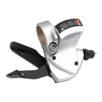
< SL-TXsGL >
To
shlft
fiorn
a
small
c-hainring to
a
larger
chainring
Whdn lever is
pr6s€d
once, there is
a
shitt of one
step lrom
a small cfiainring to a hrger chainring.
.
Example:
.
f
frcm intermediale
fchain]tu]g
to laryest
ichainring.
sL-TXs&.tN /TX3&LN
i,lon SIS
42T-gf-24f
BC
9/16' X 20
T-P.|.'(Ensllsh
throad)
BC {.37'X 24 T.P.l.
{68,
73 mm)
N.&ffi8
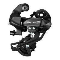
<
FD-TZ3'
I
FD.TZSO>
lnsiall
so that there is 1
-3
mm
of
doarance at the clos€st
pcint
betwsen
ihe largpst
chainring and the bottom
€dge
ol the chain
guiG.
Sr
c,EiMyam|.
2.
Ths levol
secibn of the chain
guide
outsrplate
Should
b€
ditecty
above and
parallel
to the largest chaifiing.
3. Secure u$ng a I mm spanner
(fY30,
TY10,
Tzlll, |ZSO)
or
a 5
mm Allsn
k€y
(C051,
C05O).
b*'m.Ier.hahr'ng
is
a shift ol tirie
$ep
trdlr
Us€ a handlebar
gdp
with s maximum
outer
diameler ol 32 mm.
<GS>
Add 2 links
(with
lho chain on bolh
the
largest
s:procka and ths largost
qainrins)
urgd
ta$r
gl&
ffig
J-(
<ss>
a large
cfiaindng
to
a small€r chainring.
lnstall
using ths sp€cial iool TL-UN7rl.
First install the
main body, then ths adapter.
wo
Notol
Do not
op€n
lhe
clamp of the lever when
installing, otleili6e
tha cover may be
damag€d.
.
lnstaltlh6 shiningls\ror in
a
po8ition
whore it wilt not
obstrud brake opsralion and
gear
shitting opordofl.
t
Do not
use
in
a oombination which
caus€iB brake
operation
to
b€ oostructod.
Bo surs to tollo!,v fie sequerrce
described below.
'1.
Low
adiustment
< FD-C051
/ FD-@50 / FD-TY30
/ FD.W10
>
First remove th€ PrG,Sot
alignment
block.
N6xt,
sel so that th€
dearance between
the chain
guide
inn€r
plate
and lh6
d|ain b 0
:
0.5 mm.
NdgffiM
-
Irryd
ffi
gd
ffic
diameter.
Attach
tha sarE outsr ond
cap
to tho
cl.t
gnd
of
lhe atutor
asing.
ll
'*\
!'='
+ill.
ESd
,*"*
'l.J
€D<D
<FT}'T231
IFD-TZfi>
'-Sdofiuf
m aer"r,"e
b6tYvo6ri the
cfiain
$Jire
iriner
pH€
dxl th€
cfEin b
0
-
0.5mm.
-
Urld
ffi
F*st
ffieg
2. Cinnecdon and
seordng of cable
Whil€
firmly
pulling
th6
cable, iighten the ffxing bolt with a
I
mm
spannsr
(ry30,
TYI 0, TZ31
,
TZ30)
or a
5
mm Allen ksy
(C051
,
CO50) to s€c{re the
cable.
lnsoating
th8 inner cablo
lnsort
the innor cabl€ inlothe
ouler casing ,rom the end wilh th6 markftrig
on it.
Apply
greas€
lrom the
end
with
the malkirtg in o]dor to maintain
L
cabl6
oporaling efi ciency.
Cutting the outer
casing
When
cutting the ouler
casing, cut the opoosile end
to the
F&
-
&.
snd with the'marking. After
ciiting the oirier casing,
meke
[J
t qJ
the end round
so lhat lhe insid€
of the
holo has a
unilom
v
;--lkf
,
Er$
I
I
\\kd4
1. < FD-CG51
/ FD€050
/
FD-TY3o
/ FD-W10
>
Adiust
and th6n install
the front deraill6ur
as
shown in the illustration.
Do not
remove
lh€ Pro-Sot
alignm€nt block at this time.
Ger tsth EIEuld
mwihinthis
Enge
m@
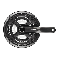
Front Derailleur
Modal numbor
F0.C051rc050 FD.TY3)
FT}TYlO FO-lz3Vfm
Fmt daEilblr iBtallafDn
band dimetsr
(lloml
type)
S,M,L
S s,M
S,M
Frcnt dorai[eur lnsisllalion
band dhrmeter
(Iop
@tE typ€)
S.M.L
S,M s,M
Chainstay
(.)
66.69"
s's'
66"{0" 66"69.
Front chainwh€61
BO
9/16' X 20 T.P.l.
(Emlish
thEad)
BC 1.37' X
24
T.P.l.
(68,
73
mm)
TyPo
Chain line
Spindle l€ngt\
Sh6ll width Stamp€d mfting ThEaddmndffi
Tdplt
47.smm
122.smm 68mm
D.NL
w1-37
X241.P.1.
'ffi@ry
a
V'I
Hghtagbbttogmmd
Emae:
&r--
ffiffi"m$i;'n-!ffi+%
+u
< SL-TX50-LN /TX3o-LN >
Pod.ri,ob.**rwi€,q&@>
Podarinsbo6m€erishb,
\
<l__
Use the conedess crank oxtractor
([L-FC10)
to install the
.lront
chainwheel.
Ssrdy tighten