Home
Shini
Heater
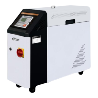
STM-HT Series
Shini STM-HT Series - User Manual
77 pages
Manual
Specs
Ask a question
Save Page as PDF
To Next Page
To Next Page
Loading...
S
T
M-
HT
S
e
r
ies
Hi
-t
e
mp
.
O
il
H
e
a
t
e
r
D
a
t
e
:
N
o
v
,
2014
V
e
r
s
ion
:
V
e
r
.
B
(En
g
li
s
h)
2
Table of Contents
Main Page
Default Chapter
3
Table of Contents
3
1 General Description
7
Coding Principle
8
Feature
8
Technical Specifications
10
Specification
10
Pump Performance
11
Reference Formula of Mould Controllers Model Selection
12
Safety Regulations
13
Safety Signs and Labels
13
Signs and Labels
14
Operation Regulations
15
Transportation and Storage of the Machine
16
Exemption Clause
17
2 Structure Characteristics and Working Principle
19
Working Principle
19
Assembly Drawing
20
Assembly Drawing (STM-907/1215-HT)
20
Parts List (STM-907/1215-HT)
21
Assembly Drawing (STM-2440-HT)
23
Parts List (STM-2440-HT)
24
Pump
26
Electrical Diagram
27
Main Circuit (STM-907/1215-HT 400V)
27
Control Circuit (STM-907/1215-HT 400V)
28
Electrical Components Layout (STM-907/1215-HT 400V)
29
Electrical Components List (STM-907/1215-HT 400V)
30
Main Circuit (STM-2440-HT 400V)
32
Control Circuit (STM-2440-HT 400V)
33
Electrical Components Layout (STM-2440-HT 400V)
34
Electrical Components List (STM-2440-HT 400V)
35
Main Circuit (STM-907/1215-HT 230V)
36
Picture 2-11:Main Circuit (STM-907/1215-HT 230V)
36
Control Circuit (STM-907/1215-HT 230V)
37
Picture 2-12:Control Circuit (STM-907/1215-HT 230V)
37
Electrical Components Layout (STM-907/1215-HT 230V)
38
Picture 2-13:Electrical Components Layout (STM-907/1215-HT 230V)
38
Electrical Components List (STM-907/1215-HT 230V)
39
Main Circuit (STM-2440-HT 230V)
41
Picture 2-14:Main Circuit (STM-2440-HT 230V)
41
Control Circuit (STM-2440-HT 230V)
42
Picture 2-15:Control Circuit (STM-2440-HT 230V)
42
Electrical Components Layout (STM-2440-HT 230V)
43
Picture 2-16:Electrical Components Layout (STM-2440-HT 230V)
43
Electrical Components List (STM-2440-HT 230V)
44
Main Electrical Components Description
45
Overload Relay
45
Picture 2-17:Overload Relay
45
Operation Procedures
46
Installation Steps for Options Water Manifold (Dewaxing)
46
Installation Steps for Options Water Manifold (Welding)
46
3 Installation and Debugging
48
Installation Space
48
Picture 3-1:Installation Space
48
Mould and Water Coupling
49
Picture 3-2:Mould and Water Coupling 1
49
Picture 3-3:Mould and Water Coupling 2
49
Power Supply
50
Picture 3-4:Mould and Water Coupling 3
50
4 Operation Guide
51
Control Panel
51
Picture 4-1:Control Panel
51
Menu Introduction
54
Machine Startup
54
Pictute 4-2:Menu Outline
54
Picture 4-3: Main Power Switch
55
Picture 4-4: Initial Menu
55
Picture 4-5: Control Setting
56
Picture 4-6: Alarm Setting
57
Picture 4-7: Output Setting
58
Picture 4-8: Temperature Setting
59
Picture 4-9: Time Setting
60
Picture 4-10: Communication Setting
61
Picture 4-11: Equipment Setting
62
Parameter Reference Table
63
Picture 4-12: Operation Screen
63
Stop the Machine
64
5 Trouble-Shooting
66
6 Maintenance and Repair
68
Open the Covers
69
Y Type Strainer
69
Picture 6-1:Open the Covers 1
69
Picture 6-2:Open the Covers 2
69
Picture 6-3:Open the Covers 3
69
Solenoid Valve
70
Pipe Heater
70
Picture 6-4:Y Type Strainer
70
Picture 6-5:Solenoid Valve
70
Cooling Pipes
71
Picture 6-6:Pipe Heater 1
71
Picture 6-7:Pipe Heater 2
71
Picture 6-8:Pipe Heater 3
71
Printed Circuit Board
72
Picture 6-9:Cooling Pipes 1
72
Picture 6-10:Cooling Pipes 2
72
Displayer Terminal Connecting Diagram
75
Maintenance Schedule
76
About the Machine
76
Need help?
Do you have a question about the Shini STM-HT Series and is the answer not in the manual?
Ask a question
Shini STM-HT Series Specifications
Print Specification
General
Model
STM-HT Series
Category
Heater
Protection Class
IP54
Temperature Range
Ambient ~ 150℃
Control Accuracy
±1℃
Heating Element
Stainless steel
Related product manuals
Shini STM-910
108 pages
Shini STM-607
108 pages
Shini STM-1220
108 pages
Shini STM-2440
108 pages
Shini STM Series
108 pages
Shini STM-W/O Series
77 pages