Do you have a question about the Shini STM-910 and is the answer not in the manual?
Provides detailed technical specifications for STM Series Oil Heaters.
Presents a table of key specifications including model, temp, power, flow, and dimensions.
Outlines essential safety rules to prevent machine damage and personal injury.
Describes various danger, attention, and warning signs with their meanings.
Explains specific warning labels and icons used on the machine.
Details operational guidelines and precautions for using the oil heater.
Provides instructions for safe transportation and proper storage of the machine.
Explains the operational flow and cycle of the oil heating system.
Presents various electrical schematics and component layouts.
Shows the main circuit diagram for STM-607/910-D at 400V.
Displays the control circuit diagram for STM-607/910-D at 400V.
Lists electrical components for STM-607/910-D at 400V.
Presents the main circuit diagram for STM-607~1220 at 400V.
Shows the control circuit diagram for STM-607~1220 at 400V.
Lists electrical components for STM-607~1220 at 400V.
Displays the main circuit diagram for STM-2440 at 400V.
Shows the control circuit diagram for STM-2440 at 400V.
Lists electrical components for STM-2440 at 400V.
Presents the main circuit diagram for STM-3650 at 400V.
Shows the control circuit diagram for STM-3650 at 400V.
Explains the function, setting, and reset procedure for the overload relay.
Provides a step-by-step guide for starting the STM oil heater machine.
Details the correct procedures for safely shutting down the machine.
Lists common failures, their possible causes, and recommended solutions for the oil heater.
Presents a schedule for routine checks and maintenance tasks.
| Frequency | 50 Hz |
|---|---|
| Temperature Control | PID control with digital display |
| Dimensions | 650 x 350 x 750 mm |
| Weight | 75 kg |
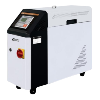
| Description | The STM-910 Mold Temperature Controller is designed to accurately control mold temperature in injection molding processes, ensuring consistent product quality and reducing cycle times. |