-9-
D2260A Mini Mobile Base Instructions
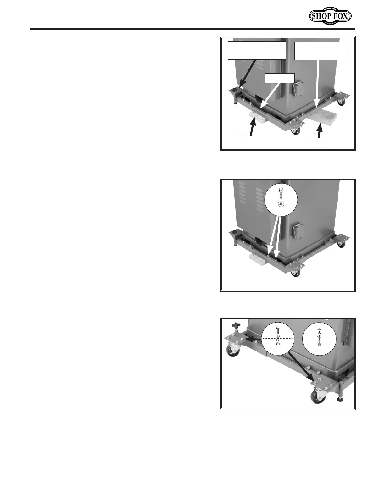
17. Whileanassistantliftsuponthebackofthe
machine,slidetherearfixedcasterassembly
ontothesiderailsofthefrontrail-cornerbracket
assembly so the rear assembly is close to the
machinebase,andthecornerpadsslideunderthe
machine,asshowninFigure 22.
—Iftherearassemblyistoonarrowortoowideto
fitontothesiderails,loosenthehexboltsthat
securethecornerbracketstotherearrail,adjust
the width of the rear fixed caster assembly so it
slidesintothesiderails,thenretightenthehex
bolts.
Tip: It may help to place a 6" 2x4 or 2x6 under the
base temporarily if you need to adjust the width
of the rear fixed caster assembly (see Figure 22).
Remove the block after you finish adjustments.
Note: You may need to tap the assembly to slide it
forward onto the side rails and under the machine.
Figure 22. Rear fixed caster assembly
inserted into front caster assembly.
FrontRail-Corner
BracketAssembly
6" 2x4
Rear Fixed
CasterAssembly
SideRail
18. Secureeachsidewith(2)M8-1.25x16hexbolts,
and8mmlocknuts,asshowninFigure 23.
Tip: Thread the hex bolts into the rails but do not
tightening the lock nuts yet.
19. Tightentheknobsenoughtoraisethecorner
brackets,soyoucanattachtheswivelcastersinthe
next step.
20. Mount each of the swivel casters to a front corner
bracketusing(4)M8-1.25x16hexbolts,8mmflat
washers,8mmlockwashers,andM8-1.25hexnuts,
as shown in Figure 24.
21. Finaltightenallofthelocknuts.
22. Remove the 2x4's from the mobile base.
23. Assembly of the mobile base is complete.
Note: The feet must not touch the floor when
moving the mobile base, and the feet must be
firmly against the floor in order to operate the
machine.
6" 2x6
Figure 24.Swivelcastersinstalled.
OR
x 4
x 4
Figure 23. Rear fixed caster assembly
secured to side rail (only one side shown).
x 2
 Loading...