-8-
D2260A Mini Mobile Base Instructions
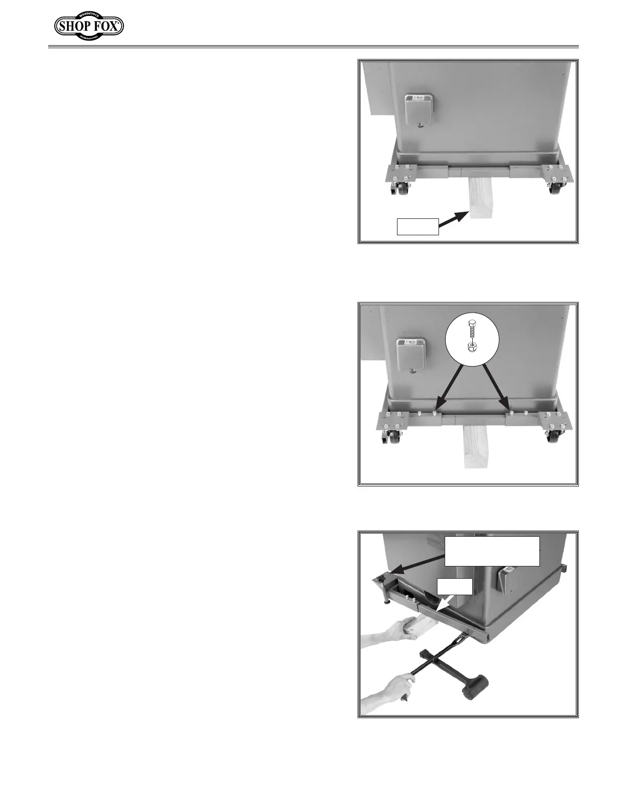
9. Withthehelpofanassistant,lifttherearsideof
themachineup,thenplacea4x4blockunderthe
machine.
10. Slideeachofthecornerbracketsintotheremaining
railandslidetheassemblyovertheblockandup
againstthemachine,asshowninFigure 19.
Note: This rail is the same size as the one you
installed on the front of the machine between the
corner brackets with the foot posts.
Figure 19. Fixed casters and rail placed
aroundbackofmachine,whichisraised
upwithawoodblock.
11. Fastenthecornerbracketstotherailwith(4)
M8-1.25x16hexbolts,and8mmlocknuts,asshown
in Figure 20.
Tip: Thread the hex bolts into the rails but do
not tightening the lock nuts against the rails until
instructed.
12. Removetherearrail-cornerbracketassemblyfrom
the4x4block.
13. Whiletheassistantsteadiesthemachine,remove
the4x4block,thensetthemachineontheground.
14. Putonsafetyglasses,useacrowbarandsometype
of fulcrum to raise one of the side rails that is
attachedtothefrontcornerbracketassembly,then
placea6"2x4undertherailtosupportit,asshown
in Figure 21.
15. Repeat Step 14 to place another 6" 2x4 under the
rail on the opposite side of the mobile base.
16. Carefullyleanthemachinetowardthefrontofthe
mobilebase,makingsuretherearenolargegaps
between the machine and the front rail-corner
bracketassembly.
Figure 20. Rear rail–fixed caster assembly
secured.
x 4
Figure 21. 2x4 placed under rail after
using crowbar to raise rail up.
FrontRail-Caster
Assembly
6" 2x4
12" 4x4
 Loading...