-7-
D2260A Mini Mobile Base Instructions
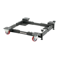
Figure 16.Cornerbracket-railassembly
placed under front of machine.
6. Slidetheotherpairofrailsthatareofidentical
sizeintotheendsofthecornerbracketsfromStep
5,thenfastenwith(4)M8-1.25x16hexbolts,and
8mmlocknuts,asshowninFigure 15.
Tip: Thread the hex bolts into the rails but do
not tighten the lock nuts against the rails until
instructed.
Figure 15.Railsfastenedtobrackets.
(Machine removed from assembly for
clarity.)
7. Whileanassistantliftsonesideofthemachineup,
slidethefrontrail-bracketassemblyfromStep 6
underthemachine,asshowninFigure 16.
Note: It may be necessary to readjust the position
of some of the fasteners once the machine is
actually on the base assembly.
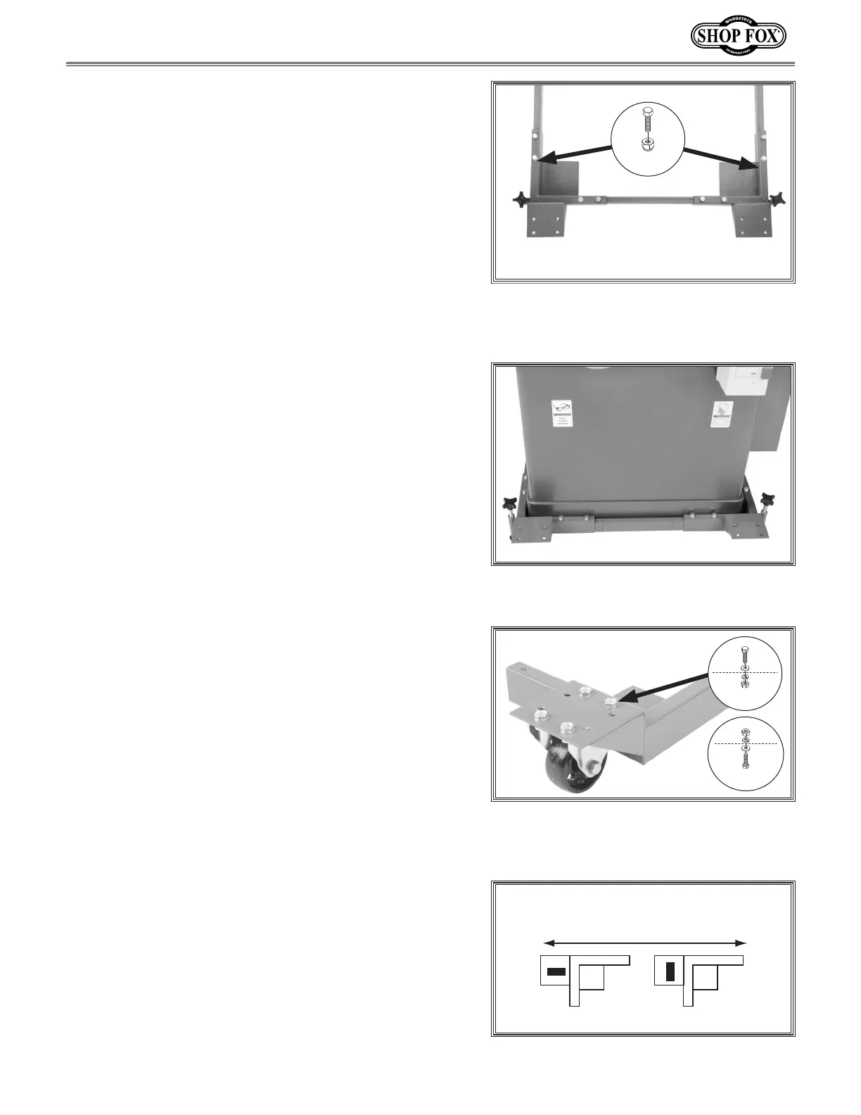
8. Mounteachfixedcastertoacornerbracketwiththe
eightholepatternusing(4)M8-1.25x16hexbolts,
8mmflatwashers,8mmlockwashers,andM8-1.25
hexnuts,asshowninFigure 17.
Orient the fixed casters so they point in the same
direction that your machine will typically be moved
(see Figure 18). Mounting the fixed casters in the
wrongdirectionwillmakeitdifficulttomoveyour
mobile base.
Note: Patience is required when installing the
fasteners inside the bottom of the fixed casters due
to space constraints.
Figure 18. Mounting casters based upon
typical direction of movement.
Kpg`ZXc;`i\Zk`fef]Dfm\d\ek
KFGM@<NF=:8JK<I
:FII<:K @E:FII<:K
x 4
Figure 17. Options for mounting fixed
casters to eight hole pattern corner
brackets.
OR
x 4
x 4
 Loading...