Operations
NOTE
• If turning has small diameter
ends, increase stock length to
keep
cutter
from
contacting
centers.
•
If
stock
has
paraffin
on
the
ends, cut
off
the ends.
Balance is extremely important
for
glued-up stock, especially long
stock
and stock that is 3" or more
in
diame-
ter. If you're gluing together
different
types of wood, arrange the wood sym-
metrically. Use one type
of
wood in
the center and the same amount
of
a
different
type of wood on the sides.
Glue the
stock
oversize to allow for
balance removal.
Examine each piece
of
wood care-
fully, even if from the same type of
tree. Check the density
of
the annual
rings. Wood with dark annual rings
spaced close together is heavier than
wood with dark rings spaced farther
apart.
To
check the balance of your spindle
or faceplate workpiece, first locate .
the centers at each end by drawing two
diagonal lines from corner to corner.
Drive
a,
standard 8 penny nail
straight
into each center. Use suitable string
to hang the
stock
in a level position
from the front bench tube of the
Mark
V.
The ends of the string should
be looped around the nails. (See Fig-
ure 1.) Gravity
will
pull the heavy side
down. Use a jointer, band saw or hand
plane to remove no more than
1/32"
at a time from the heavy side until the
stock
remains stationary when rotated
to three positions
90
degrees apart.
Locate the lathe centers or the center
of the faceplate
in
the nail holes.
Spindle
Turning
You
can turn duplicate spindles by
using a flat spindle template or by us-
ing
an
original
spindle
such as a
chair rung or
an
antique table leg for
the pattern.
(See
Figures 2 and
3.)
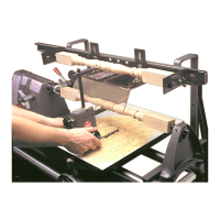
Set up
for
spindle turning according
to the following procedures:
NOTE
Initial setup of the channel and
support bracket assembly was
for
maximum spindle capacity. For
shorter pieces, the left-hand sup-
port bracket must
be
moved to the
right to allow movement
of
the
headstock toward the tailstock.
The
following
procedure assumes
that a less than maximum length
spindle is to
be
turned.
1.
Remove the left-hand support
bracket assembly. Slide the guard
(21)
to the right end of the channel
(13).
Use the 5/16" Allen wrench to loosen
the left-hand clamp screw
(18)
enough
to disengage the
clamp
(16)
from
the way tubes. Remove the screw
(19)
and washer
(20)
attaching the support
bracket
(15)
to the channel. Remove
the support bracket assembly and set
it aside. Support the left-hand end
of
the channel with your hand.
2.
Position the headstock. Position
the headstock so
that
the centers are
about 1" farther apart than the length of
the workpiece, and lock the headstock
in position.
3.
Remount the left-hand
support
bracket assembly. Place the support
bracket assembly to the right
of
the
headstock to a position which will not
interfere
with
the final
position
of
the headstock nor with proper posi-
tioning of the left-hand template sup-
port assembly. Install the support
bracket screw
(19)
and washer
(20)
fin-
ger tight, then properly align and
engage the
clamp
(16)
on the way
tubes. Tighten screw
(19)
securely.
Then, tighten screw
(18)
securely.
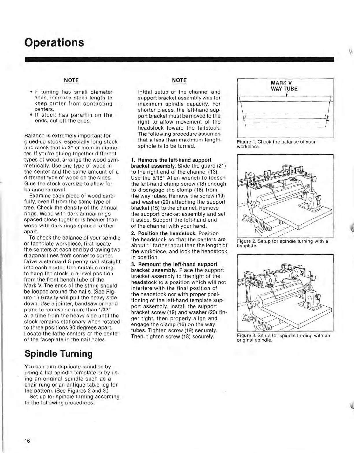
MARK
V
WAYT1UBE
1\
)
\J
oil
j
I'-
Figure
1.
Check
the
balance
of
your
workpiece.
Figure
2.
Setup
for
spindle
turning
with
a
template.
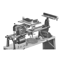
Figure
3.
Setup
for
spindle
turning
with
an
original spindle.
16
 Loading...