Assem
bl
y and
Setup
Assembly and Setup
NOTE
• Throughout the instructions,
ref-
erence numbers appear in paren-
theses following the part name.
These numbers correspond with
reference numbers on the
draw-
ings
in
this section and the Parts
List
section.
• The assembly and setup instruc-
tions for the "Table and Table
Support Assembly" are written
primarily for Mark V Models
500
and
510.
If your system is a Mark
II,
follow the instructions speci-
fied for Model
500;
for a Mark
VII,
follow the instructions specified
for Model
500
for mounting the
table supports and Model
510
for
mounting the table posts.
Before any operations can
be
per-
formed, you must assemble some
parts, set them up properly, and align
them on the Mark
V.
Your safety and
proper use of the Lathe Duplicator de-
pend on your following the Assembly
and Setup instructions exactly, espe-
cially those pertaining to your
specific
Mark V Model. If you're unsure as
to which Model Mark V you own, refer
to the NOTE on page
2.
Tools Supplied: 1/4",5/16" and 7/64"
Allen wrenches.
Tools and Supplies Required: 5/32"
standard Mark V Allen wrench, 9/16"
socket and socket wrench (or 9/16"
wrench), accurate combination square,
straightedge, mineral spirits and
flooror
furniture paste wax.
Mark V Setup
Set up the Mark V
in
the lathe mode
according
to
the following procedures:
WARNING
Turn off and unplug the Mark V
before
you
begin
any
setup
procedures.
The following procedures assume
that the worktable has been
re-
moved,
that
there
is
nothing
mounted
on
any spindles of the
machine and that all alignment
and adjustment procedures spec-
ified
in
the Mark V Owners Manual
have been completed_
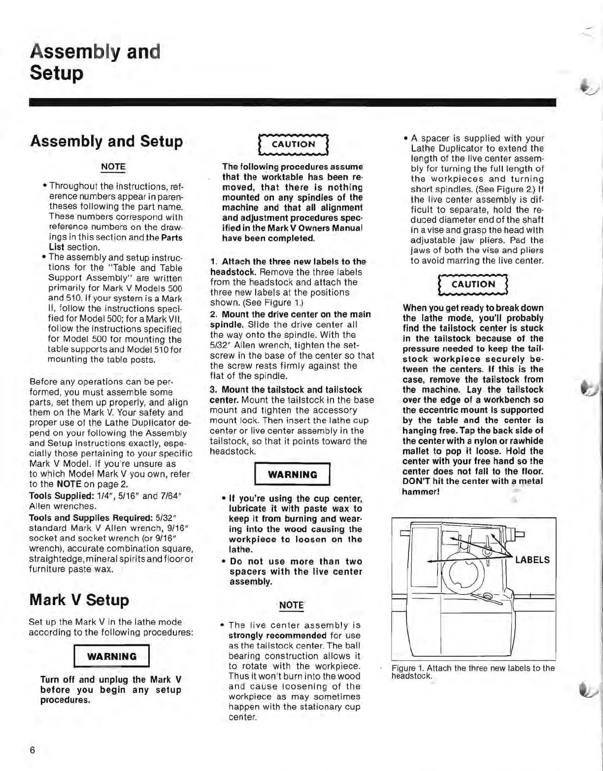
1_
Attach the three new labels to the
headstock.
Remove the three labels
from the headstock and attach the
three new labels at the positions
shown.
(See Figure
1.)
2.
Mount the drive center
on
the main
spindle.
Slide
the
drive center all
the way onto the spindle. With the
5/32" Allen wrench, tighten the set-
screw in the base
of
the center so
that
the screw rests
firmly
against the
flat
of
the spindle.
3_
Mount the tailstock and tailstock
center_
Mount the
tailstock
in the base
mount
and
tighten
the
accessory
mount lock. Then insert the lathe cup
center or live center assembly in the
tailstock, so
that
it points toward the
headstock.
WARNING
• If you're using the cup center,
lubricate it with paste wax to
keep it from burning and wear-
ing into the wood causing the
workpiece
to
loosen
on
the
lathe_
• Do
not
use
more
than
two
spacers
with
the
live
center
assembly_
NOTE
• The
live
center
assembly
is
strongly recommended for use
as the
tailstock
center. The ball
bearing construction allows it
to
rotate with the workpiece.
Thus it
won't
burn into the wood
and
cause
loosening
of
the
workpiece as may sometimes
happen with the stationary cup
center.
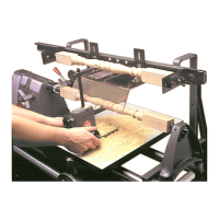
• A spacer is supplied with your
Lathe Duplicator
to
extend the
length
of
the live center assem-
bly for turning the full length
of
the
workpieces
and
turning
short spindles.
(See
Figure
2.)
If
the live center assembly is dif-
ficult
to separate, hold the
re-
duced diameter end
of
the shaft
in a vise and grasp the head with
adjustable jaw pliers.
Pad
the
jaws
of
both the vise and pliers
to
avoid marring the live center.
When
you
get ready to break down
the lathe mode, you'll probably
find the tailstock center
is
stuck
in
the tailstock because of the
pressure needed to keep the tail-
stock
workpiece
securely
be-
tween the centers_ If this is the
case, remove the tailstock from
the machine_ Lay the tailstock
over the edge of a workbench so
the eccentric mount
is
supported
by the table and the center is
hanging
free_
Tap the back side of
the center with a nylon or rawhide
mallet to pop it
loose_
Hold the
center with your free hand so the
center does not fall to the
floor_
DON'T hit the center with a metal
hammer!
£....,.~~'f.--;;-
LABELS
Figure
1.
Attach
the three new labels
to
the
headstock.
6
 Loading...