--
Assembly
and
Setup
4.
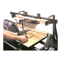
Align the lathe centers.
(See
Figure
3.)
Align the drive
center
and the
tailstock
center. (Refer
to
the Mark V
Owners ManuaL)
Both the drive center and the tail·
stock center must
be
directly
in
line with each other
in
order to
properly support a workpiece
so
that it can
be
turned.
SPACER
~6~
D
~
LIVE CENTER
Figure
2.
The spacer extends the length
of
the live center assembly.
DRIVE
Figure
3.
Both the drive center and tailstock
center must
be
directly
in
line with each
other
in
order to properly support a
workpiece.
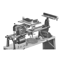
Tool Rest Assembly
Assemble the tool rest assembly ac-
cording
to
the
following
procedures:
1.
Attach handles. Screw handles (52)
secu rely onto st uds
of
tool
rest
base
(37).
2.
Install the cutter support. Insert the
cylindrical end of the
cutter
support
(58) into the tool rest base
(37)
until the
position indicating groove is flush
with the face
of
the base. Rotate the
cutter
support until the cutter·mount-
ing flat of the
cutter
support is paral-
lel
with
the base.
Use
the 5/32" Allen
wrench
to
tighten the
cutter
position-
ing setscrew
(42)
until it firmly
engages the V-groove of the
cutter
support, then back
off
1/4 turn.
NOTE
Seating the cutter positioning set·
screw in its groove in the
cutter
support will cause the position in·
dicating
groove to move
slightly
inward or outward from the face
of the tool rest base. Loosening
the setscrew
1/4 turn will allow ro-
tation
of
the cutter support and
approximately 1/16" in and out
movement.
3. Install the cutter adjusting knob.
Screw the
cutter
adjusting
knob
(51)
into the base (37) until the end
of
its screw
contacts
the back
of
the cut-
ter support
(58).
4.
Install the follower upright. With its
flat
at
the
top, and facing toward
the back of the base, insert the follower
upright
(50)
into the top hole
of
the
base (37)
until
it
contacts
the
cutter
support (58). Use the 5/32" Allen wrench
to
tighten the setscrew (41)
lightly
against the follower upright.
5.
Install the follower adjusting knob
and the follower support.
Install the
setscrew
(45)
into the knob
(44)
with the
cup point
facing
out -of the knob.
Thread the knob with setscrew
'"
installed into the follower support (46).
Slide the follower support over the
flat
of
the follower upright
(50)
and
tighten the knob.
NOTE
Wiggle the follower support as
you tighten the knob to properly
seat the cup point
of
the screw
against the flat of the follower up·
right. When properly assembled,
the setscrew will remain in the
knob when knob is loosened
to
adjust the follower.
. 6. Install the carbide cutter and cutter
guide.
Attach the triangle carbide
cutter (57), with the bevel down,
to
the
cutter support
(58)
with
screw (56)
finger tight. Any
of
the
cutter's
three
points or flats may
be
positioned as
shown in Figure
4.
With the open
slot end of the cutter guide
(55) pressed
firmly against a flat side
of
the car·
bide cutter, use the
7/64" Allen wrench
to
attach the cutter guide securely
to
the cutter support
with
screw (53)
and washer
(54).
Then, securely tighten
the screw (56) of the carbide cutter.
NOTE
Carbide
cutters
come
in
four
shapes for a variety of purposes:
•
Triangle:
Universal
cutter-
rough shaping through medium
detailing
.
(Included
with
the
Lathe Duplicator.)
• Round: Initial sh,:.ping, graceful
curves, cove cut>, dishing.
• Diamond: Fine beads, deep in-
tricate details, V-grooves, sharp
corners.
•
Square
:
Square
corners,
grooves,
straight
cylinders,
short dowels and plugs.
TRIANGLE
(2
POSITIONS)
I
c(@)
Gf:®>
DIAMOND
I<®p
C@
I
(@p~
ROUND SQUARE
Figure 4. Mounting positions
of
carbide
cutters and cutter guides.
7
 Loading...