2 | SHOREMASTER.COM
TABLE OF CONTENT
*RS4 Bundle*
DESCRIPTION
PART NUMBER
QTY
ITEM
Frame 4 x 10100368718
Frame 4 x 4
10036951
(8)
Frame 4 x 1210036881
(8)
Frame 6 x 810038081
(8)
Foot Pad 100652329
Bolt Bag - Listed at Left
10044251
-
Infinity Dock Pocket
100659121 0
*1004425 - Bolt Bag - RS-4 Dock System*
DESCRIPTION
PART NUMBER
QTY
ITEM
T-Handle 3/8 x 1.5
100087621
Connector Clip
100465122
Nut 3/8 Brass
100180323
Bolt Carriage 3/8 X 1.0
100195624
Nut Flange 3/8
10018022
5
Blue Cap
100181526
Corner Cap
10008754
7
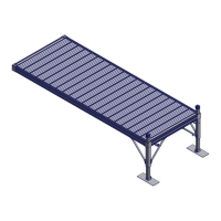
Infinity Dock System
RS4 Section
Part Numbers:
4 x 4 Section - 1004214
4 x 10 Section - 1005986
4 x 12 Section - 1005987
6 x 8 Section - 1005989
Decking Type 2' PANELS 1' PANELS
Cedar Wood Deck 1007557
Plain Aluminum Deck 1007546
Ipe Hardwood Deck 1007564
White Aluminum Deck 1007567
Tan Aluminum Deck 1003442
Tan Vertex Deck 1004074
Titan Deck 1024039 1021586
LEG POSTS PART #
3' DOCK LEG POST (each) - 1003556
5' DOCK LEG POST (each) - 1000157
7' DOCK LEG POST (each) - 1000158
9' DOCK LEG POST (each) - 1000159
12' DOCK LEG POST (each) - 1000160
PARTS LIST "A"
PARTS LIST "B"
7
A
2
A
1
A
3
A
6
A
8
B
LEGS SOLD SEPERATELY
(CHOICE OF SIZE - 3', 5',
7', 9', AND 12')
4
A
5
A
10
B
9
B
Table of Contents................................................................................................................................................................................2
Parts and Components...................................................................................................................................................................3-4
Assembly Instructions.................................................................................................................................................................5-8
Common Doc k Accessories................................................................................................................................................................9
Accessory Installation...............................................................................................................................................................10-24
Warranty Information................................................................................................................................................................25-27
Installation Tools Needed:
DETAIL A
A
ASSEMBLY INSTRUCTIONS
Your safety is the most important issue related to this product.
Fully read and understand each step before proceeding with that step.
Wear protective gloves, clothing and eyewear when assembling and installing the lift.
Do not assemble, install or use this product if items are missing or damaged.
Leave all hardware finger tight until lift is completely assembled, then tighten all hardware.
For ease of assembly find a flat area with plenty of room to assemble lift. The following tools will be
needed for assembling lift:
1. 7/16" Wrench 5. Tin Snips (to open bundle)
2. Two 9/16" Wrenches 6. Vise Grip
3. Measuring Tape 7. Hammer
4. Sharp Knife or Razor 8. Square
STEP 1
Slide Blue Caps on uprights as shown. Insert all four Leg Posts into Foot Pads, secure using one 3/8
x 2 3/4 Hex Bolt and one 3/8 Brass Nut in each place. Insert Leg Posts into V-Side Lift and Opposite
Lift Side as shown. Use one 3/8 x 2 3/4 Hex Bolt, two 3/8 Flat Washers and one 3/8 Brass Nut for
each Leg Post.
Blue Cap
Foot Pad
Leg Post
Lift Side
3/8 Brass Nut
3/8 Flat Washer
3/8 x 3.0 Hex Bolt
3/8 x 2 3/4 Hex Bolt
3/8 Brass Nut
Lift Opposite Side
V-Side
 Loading...