SHOREMASTER.COM | G
ASSEMBLY INSTRUCTIONS
ASSEMBLY INSTRUCTIONS
DETAIL B
DETAIL A
B
A
Tools needed:
1. 9/16” Wrench
2. Measuring Tape
3. Optional - Carpenter's Level
Tips:
Before assembly determine the layout of the dock system.
Take depth measurements at ten foot intervals starting at
where the dock will start.
Have adequete dock leg lengths to accommodate water
fluctuation and waves.
For ease of assembly find a flat area with sufficient room to
assemble dock.
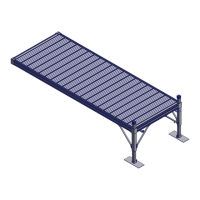
STEP 1
After determining the layout of your Dock System, install all
Leg Pockets according to their instructions. The number and
location of Leg Pockets will depend on the specific layout
and the type of Leg Posts.
STEP 2
Attach one Foot Pad to each Leg Post. Secure Leg Post with
one 1/2 x 1 1/4 Set Screw and one 1/2 Square Nut per leg.
Note: Leg Posts are ordered separately from dock section
because of varying lengths needed.
STEP 3
Determine which side of the RS4 Frame will be connected to
other sections. Insert one 3/8 Nut into each Connector Clip
and thread the 3/8 x 1 1/2 T-Handle through it just so they
stay together - as shown in Detail "A".
Attach Connector Clips to the Rail. Secure with one 3/8 x 1
Carriage Bolt and one 3/8 Flange Nut. The Carriage Bolt
head inserts into the opening in the bottom slot of the Rail
and attaches to the Connector Clip - as shown in Detail "A".
Place the Connector Clip six inches or less in from the
Corner - as shown in Detail "B".
NOTICE: A Rail six feet or less requires two Connector
Clips. Rails greater than Six feet need a third connector in
the middle of the connection.
CAUTION: Make sure the Connector Clip
assembly is fully clear of the Opening in the slot.
Corner
Connector Clip
6"
ASSEMBLY INSTRUCTIONS
3/8 Nut
T-Handle
Connector
Clip
3/8 Flange Nut
T-Handle
DETAIL A
D
E
A
G
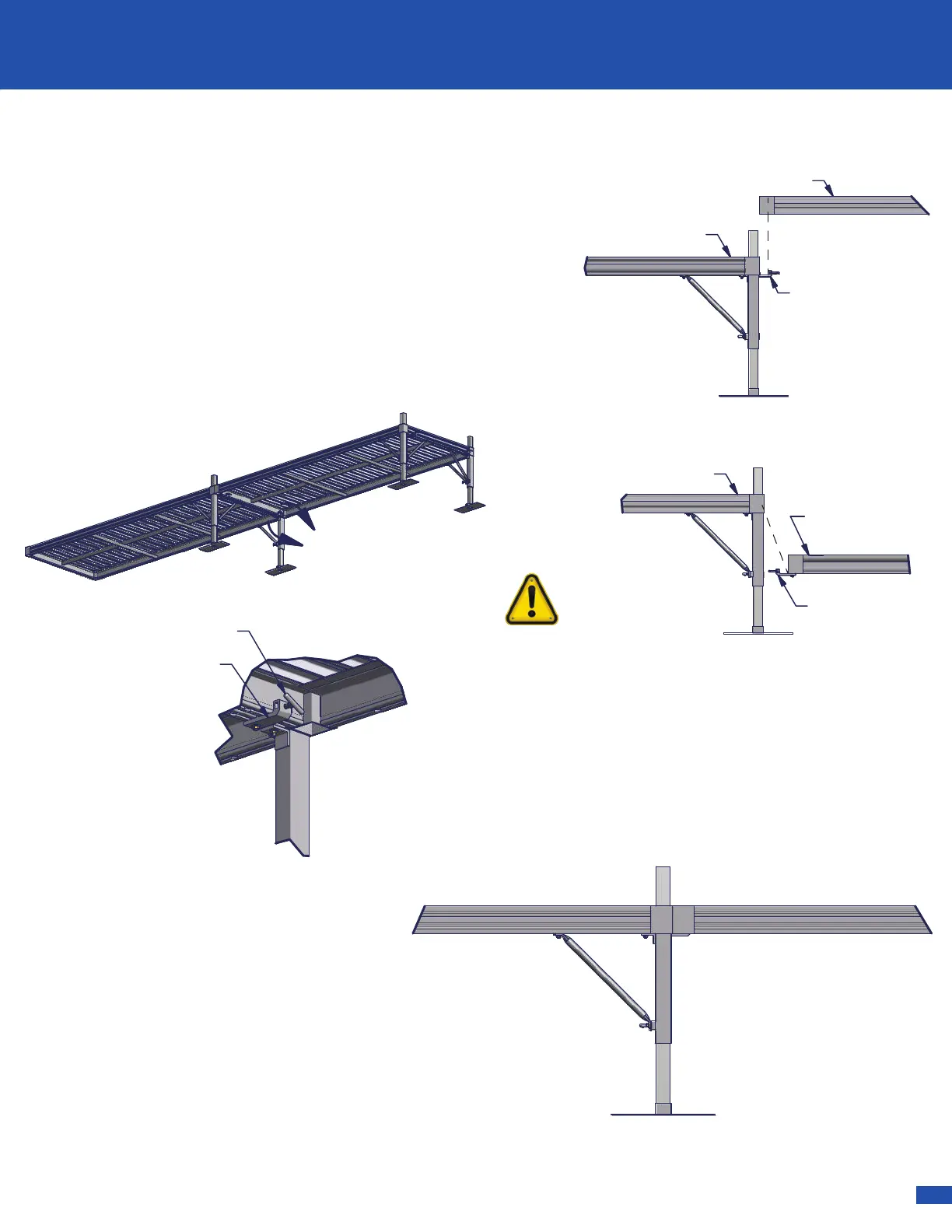
STEP 4
Now the first Frame can be carried into place. Place the second
Frame into the Connector Clips of the first - as shown to the
right.
CAUTION:
The Connector Clips must be bolted to a dock
frame that is supported by legs. The unsupported end of the
attaching dock frame will set into the Connector Clip.
Secure by tightening the 3/8 x 1 1/2 T-Handle - as shown in
Detail "A."
Note: Two Connector Clips are needed if connecting to an End
Rail. Three are needed if connecting two Side Rails together.
Supported Frame
Unsupported Frame
Supported Frame
Unsupported Frame
Good Connection
Bad Connection
Connector Clip
3/8 x 1 1/2 T-Handle
Connector Clip
Connector Clip
STEP 5
When all RS4 Frames are in place, adjust
the level of the dock sections as needed
using the adjustable leg posts.
Note: Make sure there is enough
clearance for water flucuation and wave
action.
Fully tighten all Nuts and Bolts.
Note: Do not over tighten set screws. Over
tightening of set screws will result in
bending or breaking of parts.
!
 Loading...