E N
Nome file:
7540028EN - CUSTOMER MANUAL SF15_200 TOP EN.docx Rev. 1 12/06/2017
13-28
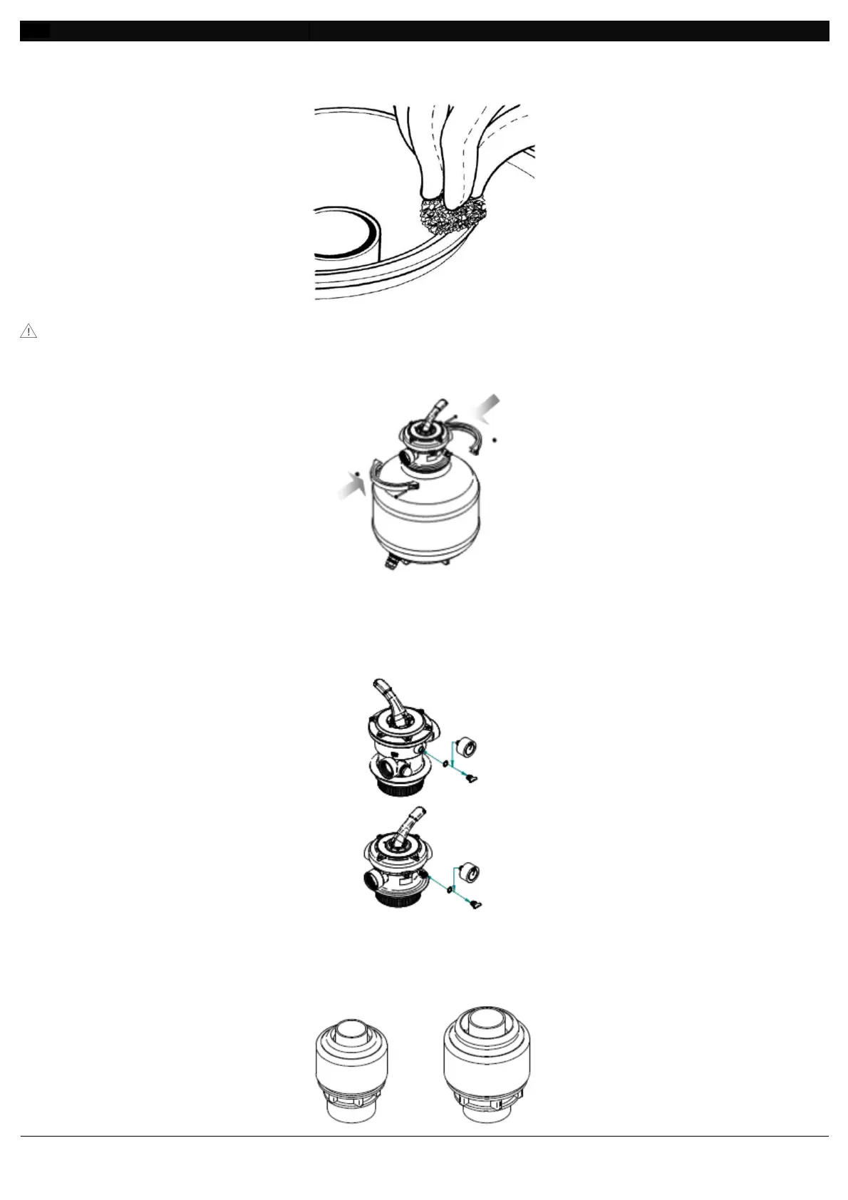
5. Clean really carefully the tank’s neck, place the multifunctional valve taking care that the tube enter
in the central hole (Fig. 17).
Fig. 17
Insert the pipe into the central hole, taking care not to move the O-ring from its housing.
6. Now fix the multifunctional valve to the tank through the supplied flange (Fig. 18). Work with a
screwdriver to tight the screws.
Fig. 18
7. Take off the multifunction white multifunctional valve cap, apply some supplied teflon around the
manometer (optional for SF15, 25) thread and then screw the manometer with a key using no strength
on the plastic box (Fig. 19).
Fig. 19
Now your filter is at your disposal.
Pressure connection with compression fittings (optional).
5.6.3
See Fig. 20.
 Loading...