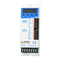
The SHS HT3 series is a range of microstepping motor drives designed for controlling stepping motors. This manual provides detailed information on the technical characteristics, connections, settings, function modes, and command tables for the HT3 series.
Function Description
The HT3 series drives are designed to control stepping motors, offering various operation modes including Step/Direction, Modbus Fieldbus protocol, Winstar Fieldbus protocol, and CanOpen protocol. The drives execute a single step for each rising edge of the step-in signal in Step/Direction mode, with IN4 acting as the step-in clock, IN5 defining the direction of rotation, and IN6 enabling the drive. The drives are capable of handling both digital and analog inputs/outputs, with isolation from the power supply for digital I/O. Analog inputs and outputs are not isolated.
Important Technical Specifications
DC Power Supply (1.2 DC power supply, page 4):
The HT3 series offers two models, HT320 and HT350, with different voltage and current specifications:
- HT320:
- Nominal Voltage (Vdc nom): 24V
- Maximum Voltage (Vdc max): 30V
- Minimum Voltage (Vdc min): 18V
- Maximum Phase Current (I max): 4A
- Minimum Phase Current (I min): 0.1A
- HT350:
- Nominal Voltage (Vdc nom): 48V
- Maximum Voltage (Vdc max): 70V
- Minimum Voltage (Vdc min): 18V
- Maximum Phase Current (I max): 8A
- Minimum Phase Current (I min): 1.0A
Both models share:
- Operating Temperature: 0-45°C (For continuous working with phase current > 6A, forced cooling is necessary).
- Logic Power Supply Output (Vcc): 15V
- Logic Power Supply Current Maximum (Icc max): 0.1A
Digital Inputs & Outputs (1.3 Inputs & Outputs, page 5):
- IN1, IN2, IN3 (PNP compatible):
- Low Level: 0V to 7V (Standard), 0V to 2.5V (TTL)
- High Level: 9V to 24V (Standard), 3.5V to 5V (TTL)
- Max Current: 6mA (Standard), 5mA (TTL)
- IN4, IN5, IN6 (NPN/PNP selectable):
- Low Level: 0V to 7V (Standard), 0V to 2.5V (TTL)
- High Level: 9V to 24V (Standard), 3.5V to 5V (TTL)
- Max Current: 10mA (Standard), 4mA (TTL)
- Outputs (OUT1, OUT2, OUT3 - NPN/PNP selectable):
- PNP Output: ON (COM OUT VOLTAGE - 2V), OFF (0V)
- NPN Output: ON (2V), OFF (COM OUT VOLTAGE)
Analog Inputs & Outputs (1.3 Inputs & Outputs, page 5):
- Analog Inputs:
- Range: 0 to 10V
- Impedance: 150 KΩ
- Analog Outputs:
- Range: 0 to 10V
- Max Current: 10 mA
Connectors (2.1 Input/Output connector, page 6):
The J2 connector handles various signals including Fieldbus (FB-, FB+), GND, Analog Inputs (AIN1, AIN2), Reference Voltage Output (VREF), Analog Output (ANOUT), Auxiliary Voltage Output (+VCC), Inputs (IN6 EN, IN5 DIR, IN4 CLK, IN3 CHZ, IN2 CHB, IN1 CHA), Common References (COMIN B, COMIN A), and Outputs (OUT3, OUT2, OUT1, COM OUT).
The J1 connector handles power supply and motor phases:
- B2, B1, A2, A1: Motor phases
- OV: OV power supply
- +HV: DC power supply input
HT3 Models Code (5. HT3 MODELS CODE, page 20):
The model code HT3x1KK - yyyyy / Zzz indicates:
- x: Size (2 = 4A 20..28Vdc, 3 = 4A 20..60Vdc, 5 = 8A 20..60Vdc)
- KK: Fieldbus (WS = RS485 SHS Protocol, MB = Modbus, CO = CanOpen)
- yyyyy: Option code (sum of enabled options: 1=Encoder TTL, 2=Input TTL, 4=Display Bootm, 8=EEprom special Firmware, 16=Signal crimp connector, 32=Power Screw connector, 64=IN6 Disable input, 128=IN6 spare input)
- Zzz: Special Version (Dzz = Dedicate Software, Szz = Modify Hardware)
Usage Features
Safety (Security notes, page 2):
- SHS automation products must be handled, installed, and maintained by competent personnel only.
- Installation instructions of components and safety regulations must be followed.
- The device is designed for industrial environments and requires proper grounding and protection against electrical hazards.
- Only qualified persons should handle the device due to the risk of electric shock.
- Always check drive power terminals when voltage is removed.
Enable Input (2.3 Enable Input, page 7):
To switch on the power of the motor, a signal must be connected to Enable Input (IN6). Without this signal, the drive stops the motor, and there is no deceleration ramp, and the motor phases current goes to zero. If IN6 is a Disable Input, drive models table option is used. If IN6 is an Enable Input, an spare input, drive models table option is used.
Encoder (2.4 Encoder, page 7):
Encoder connection is used to check the motor position.
Parameters Setting (3.1 Parameters setting, page 8):
Parameters are set using buttons below the display.
- Access main menu: Press [v] for two seconds.
- Select parameter: Press [V] or [▲].
- Visualize actual value: Press [v].
- Change value: Press [V] or [▲].
- Store value: Press [v] for two seconds ("memo" appears on display).
- Return to main menu without modifying: Press [◆].
- Exit main menu: Press [◆].
- Password parameter: Use [◆] to move the pointer between characters.
Display Messages (3.2 Display messages, page 8):
The display shows various status messages:
rdy: Drive OK, motor stoprun: Motor runningdis: Drive disabledtemp: Over temperature ErroruvoL: Under Voltage ErrorovoL: Over Voltage Errorocur: Over Current Errorperr: Generic ErrorrSt: Reset phase
In case of error, the drive removes power to the motor. Over current and generic errors require switching the drive off and on to reset. Over temperature, under voltage, or over voltage errors require the correct value to be restored.
Function Modes (4. FUNCTION MODES, page 9):
The drive supports different function modes:
- "PD": Step/direction command
- "Modb": Modbus Fieldbus protocol
- "Win": Winstar Fieldbus protocol
- "CanO": CanOpen Fieldbus protocol
Basic Drive in Step Direction mode does not have a Mode option. Winstar and Modbus drives can have Step/direction mode.
Step Direction Mode "PD" (4.1 Step Direction Mode "PD", page 10):
- Opar (Reset Eeprom values): On (Unaffected)
- curr (Set the phase current [mA]): See drive models table option (1000)
- res (Set the resolution [1/n steps]): 1/1, 1/2, 1/4, 1/8, 1/16 (1/2)
- redi (Set the reduction current value): Zero Current, Imax/4, Imax/2, Imax (Imax/4)
- redt (Set the reduction current time): 10ms to 300ms (10)
- Firm (Firmware Release): Variable (Unaffected)
- pass (Password): Alphanumeric value ("----")
Modbus Mode "MODB" (4.2 Modbus Mode "MODB", page 11):
The drive supports MODBUS-RTU protocol. Data format is N,8,1.
- baud (BaudRate RS485[Kbps]): 9.6, 19.2, 38.4, 57.6, 115.2 (19.2)
- par (Parity RS485): "no", "even", "odd" ("no")
- Addr (Node Modbus Address): 0 to 31 (1)
- Mode (Mode Function): "PD", "Modb" ("Modb")
Winstar Mode "Win" (4.4 Winstar Mode "Win", page 14):
The drive supports WINSTAR proprietary protocol. Data format is N,8,1.
- baud (BaudRate RS485[Kbps]): 9.6, 19.2, 38.4, 57.6, 115.2 (19.2)
- par (Parity RS485): "no", "even", "odd" ("no")
- Addr (Node Modbus Address): 0 to 31 (1)
- Mode (Mode Function): "PD", "Win" ("Win")
Command Table (4.5 Command table, page 15):
The device supports various commands for control and monitoring, including:
- 0x01 (DRIVE RESET): Stops motor, initializes speed and ramp to 0.
- 0x02 (SOFTWARE START): Starts motor according to transmitted values.
- 0x10 (Request for software version): Returns software version.
- 0x11 (IMMEDIATE STOP): Slows motor down according to set ramp.
- 0x12 (READING OF CURRENT POSITION): Returns instantaneous motor position (4 bytes).
- 0x16 (POWER VOLTAGE READING [V]): Returns power voltage.
- 0x17 (RAMP SETTING): Sets ramp inclination (2 bytes, max 10000).
- 0x20 (SETTING OF MINIMUM FREQUENCY): Sets minimum frequency (2 bytes, range 1 to 10000 Hz).
- 0x21 (SETTING OF MAXIMUM FREQUENCY): Sets maximum frequency (2 bytes, range 1 to 40000 Hz).
- 0x22 (SETTING OF RAMP INCLINATION): Sets ramp inclination (1 byte, range 1 to 255).
- 0x23 (SETTING OF HOME POSITION): Associates entered value to home position (4 bytes).
- 0x26 (SETTING OF MOTOR RESOLUTION): Sets motor resolution (1 byte, 0=1/1 to 4=1/16).
- 0x27 (SETTING OF ELECTRIC CURRENT REDUCTION): Sets current reduction mode (1 byte).
- 0x29 (TRIGGER START (LOGIC AND)): Defines input/levels for starting motor by external command.
- 0x2A (TRIGGER STOP (LOGIC AND)): Defines input/levels for stopping motor by external command.
- 0x30 (ABSOLUTE POSITIONING (RELATIVE TO THE HOME POSITION)): Sets absolute position (4 bytes).
- 0x31 (RELATIVE POSITIONING): Sets relative position (4 bytes).
- 0x32 (INFINITE MOTION): Sets rotation direction (1 byte, 0=CW, 1=CCW).
- 0xA0 (ZERO AT FLIGHT (LOGIC AND)): Defines input/levels for zeroing position at flight (5 bytes).
- 0xA3 (2 BYTES DRIVE STATUS): Returns drive status (2 bytes).
- 0xA6 (MOTION TO ZERO VALUE): No parameter.
- 0xA8 (CURRENT SETTING): Sets current value (2 bytes).
- 0xAA (SETTING OF RELATIVE VALUE (WITHOUT ANY POSITIONING)): Sets relative value (4 bytes).
- 0xAB (2 BYTES DRIVE STATUS): Returns drive status (2 bytes).
- 0xAE (SETTING OF ABSOLUTE POSITION): Sets absolute position (4 bytes).
- 0xAF (AXIS ZEROING): Defines input/levels for axis zeroing (1 byte).
- 0xB0 (LIMIT SWITCH (LOGIC AND)): Defines input/levels for limit switch (1 byte).
- 0xB2 (ZERO AT FLIGHT MASK QUOTE): Enables zero at flight trigger after quote (4 bytes).
- 0xB6 (SETTING OF ABSOLUTE VALUE): Sets absolute value (4 bytes).
- 0xB7 (LIMIT SWITCH (LOGIC OR)): Defines input/levels for limit switch (1 byte).
- 0xC0 (TRIGGER MODE): Sets trigger mode (1 byte, 0=one shot, 1=always enabled).
- 0xCA (OUTPUTS SET): Sets outputs (1 byte).
Maintenance Features
General Maintenance (Security notes, page 2):
- The device must be installed and maintained by competent personnel.
- Regular checks of the drive power terminals are recommended, especially when voltage is removed.
- In case of errors, the drive will remove power to the motor.
- Over current and generic errors require switching the drive off and on to reset.
- Over temperature, under voltage, or over voltage errors require the correct value to be restored for reset.
- For continuous working with phase current > 6A, forced cooling is necessary to maintain the operating temperature within the specified range (0-45°C).
The manual emphasizes that any modifications or variations made to the drive systems are forbidden and invalidate any right to warranty interventions or any liability obligation.