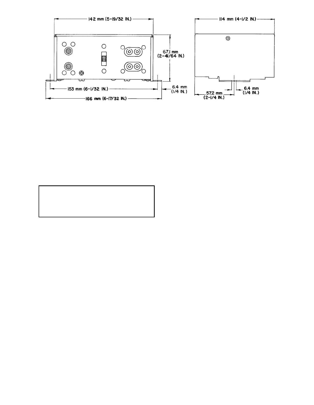
OVERALL DIMENSIONS
FIGURE 2
to the “Ground” screw on the Preamplifier
chassis.
d. If ac power operated, insert the M64 or M64-2E
power line cord into a proper power outlet,
preferably one controlled by the power am-
plifier’s On-Off switch. Be sure power switch
on M64 or M64-2E is in the “On” position
when remotely turned “On” & “Off”.
WARNING
Voltages in this equipment are hazardous
to life. Refer servicing to qualified service
personnel.
Balanced Line Output:
For professional low-impedance balanced line
use, such as broadcast systems or recording con-
soles, an external line matching transformer (Shure
Model A95 Series) may be added to each High
Level output of the M64 or M64-2E. The resultant
output level will be approximately -32 dBm. If a
higher output level is necessary (-20 dBm) the
following change can be made by qualified service
personnel only, which will increase the output level
by approximately 12 dB.
1. Unplug the ac line cord before removing
cover.
2. Remove the three large Phillips head screws
that hold the case cover in place.
3. Lift off cover.
4.
Remove printed circuit board assembly from
nylon fasteners by squeezing upper protrud-
ing tab on circuit board side inward and sliding
board outward and off the fastener.
5. Lift the printed circuit board assembly straight
up until 1 k resistors R13 and R14 are ac-
cessible. (See bottom illustration on page 4)
Note R13 and R14 are raised on longer leads
than the other resistors for ease of identifi-
cation.
6. Solder 330 ohm ¼ watt resistors across (in
parallel with) the extended lead wires of R13
and R14 (330 ohm resistor across the 1000
ohm resistor). The extra lead length of R13
and R14 makes this very easy and it is not
necessary to alter the printed circuit board or
its components.
7.
Remount the printed circuit board assembly
and replace the cover, being careful not to
pinch any wires when closing up the unit.
NOTE: This change will decrease the input
clipping level of the preamplifier to about 25
mV so that if high-output cartridges or very
highly modulated records are used the pre-
amplifier may tend to clip on loud passages.
If the gain increase desired is less than 12 dB,
the following resistors can be used in parallel
with R13 and R14 instead of the 330 ohm
resistors.
for 3 dB, use 2.2 kilohms
for 6 dB, use 1 kilohm
for 9 dB, use 560 ohms
FULL ONE-YEAR WARRANTY
Shure Brothers Incorporated (“Shure”), 222
Hartrey Avenue, Evanston, Illinois 60204, warrants
to the owner of this product that it will be free, in
normal use, of any defects in workmanship and
materials for a period of one year from date of pur-
chase. You should retain proof of date of purchase.
Shure is not liable for any consequential damages.
If this Shure product has any defects as described
above, carefully repack the unit, have it insured, and
return it prepaid to:
Shure Brothers Incorporated
Attention: Service Department
222 Hartrey Avenue
Evanston, Illinois 60204
If you are not in the United States, return the unit
to your dealer or Authorized Service Center for
repair. The unit will be repaired or replaced and
returned to you promptly, and if it cannot be re-
paired or replaced, you may elect to receive a
refund.
 Loading...