EasyManua.ls Logo

Shure M64 User Manual

Shure M64
4 pages
To Next Page IconTo Next Page
Page #1 background imageLoading...
Page #1 background image
222 HARTREY AVE., EVANSTON, IL, 60204 U.S.A.
AREA CODE 312/866-2200 • CABLE: SHUREMlCRO
DATA SHEET
TWX: 910-231-0048
TELEX: 72-4349
MODELS M64 AND M64-2E
MICROPHONES AND ELECTRONIC COMPONENTS
STEREO PREAMPLIFIERS
GENERAL
The Shure Models M64 and M64-2E Stereo Pre-
amplifiers are designed to furnish the voltage gain
and equalization necessary to operate magnetic
phono cartridges (such as the Shure DYNETIC
®
Cartridges), and tape playback heads with audio
amplifiers that have no equalization. In addition, the
units may be used without equalization for micro-
phones or as buffer amplifiers.
Typical Applications:
l Conversion of stereo record playing systems
from ceramic to magnetic cartridges.
l Preamplifier for microphones.
l Low gain buffer amplifier where long cable
lengths are extended to a preamplifier input.
Advantages include complete freedom from micro-
phonics, extremely low noise, the ability to use
15m (50 ft) or more of output cable, and years of
maintenance-free performance. The operating tem-
perature range is from 7°C (20°F) to 57°C (135°F).
The Model M64 operates on 108-132 volts, 50/60
Hz power line, or from an auxiliary 24 to 36 volt dc
supply such as the Shure Model A67B Battery Power
Supply. The M64-2E is identical to the M64 except
that it operates on a line voltage of 216-264 volts,
50/60 Hz.
The Model M64 and M64-2E feature a single 3-
position slide switch for selecting equalization for
Phono, Tape, or Flat. The Phono position provides
the Standard RIAA Equalization for phono records.
The Tape position provides the Standard 7½ IPS
NAB Equalization for tape, and the Flat position
provides a flat amplifier for microphones or as a
buffer amplifier for magnetic phono cartridges when
long lines or switching systems are necessary
between the turntable and main equalized pre-
amplifier. (NOTE: When used as a buffer amplifier,
the Low Level Outputs should be used). The input
and output jacks will accept standard phono plugs.
There are input jacks for Channel 1 and Channel 2;
output jacks for Ch. 1 High Level, Ch. 1 Low Level,
Ch. 2 High Level, and Ch. 2 Low Level.
Copyright 1984, Shure Brothers Inc.
27A2076 (DB)
SPECIFICATIONS
Gain
Gain measured at 1 kHz with input through 680
ohms and output terminated in 47 kilohms.
Equalization
High Level
Low
Level
Switch Position output
output
Flat
+27.5 dB
+ 4.0 dB
Phono
+34.5 dB
+11.0 dB
Tape
+37.0 dB +13.5 dB
Frequency Response
Flat:
± 2 dB from 20 Hz to 20 kHz
Phono:
± 2 dB of the Standard RIAA curve from
40 Hz to 15 kHz
Tape:
± 2 dB of the 7½ IPS NAB curve from
50 Hz to 15 kHz
TYPICAL FREQUENCY RESPONSE
FIGURE 1
Distortion
Under 1% total harmonic distortion for an output
of 2 volts at 1 kHz in Phono, Tape or Flat positions.
In the Phono position the total harmonic distortion
is less than 1% at 30 Hz with 2 volts output.
Clipping Level
The minimum input clipping levels at 1 kHz are:
Flat: 250 mV
Phono: 100 mV
Tape: 80 mV
Channel Separation
50 dB or better at 1 kHz
Channel Balance
Channels matched within 2 dB at 1 kHz
Printed in U.S.A.
Question and Answer IconNeed help?

Do you have a question about the Shure M64 and is the answer not in the manual?

Shure M64 Specifications

General IconGeneral
BrandShure
ModelM64
CategoryAmplifier
LanguageEnglish

Summary

General Information and Applications

Typical Applications

Lists common uses like converting record players, preamplifying microphones, and extending cable lengths.

Product Advantages

Highlights benefits such as low noise, freedom from microphonics, and long output cable use.

Model Operation and Differences

Explains the difference between M64 and M64-2E voltage operation and switch functionality.

Specifications Overview

Gain Specifications

Details gain levels for 1 kHz input at High Level and Low Level outputs for different equalization settings.

Frequency Response Details

Defines frequency response for Flat, Phono (RIAA), and Tape (NAB) settings.

Distortion Limits

Specifies total harmonic distortion limits at 1 kHz and at 30 Hz for Phono position.

Input Clipping Levels

Lists minimum input clipping levels at 1 kHz for Flat, Phono, and Tape positions.

Channel Separation

States channel separation is 50 dB or better at 1 kHz.

Channel Balance

Indicates channel balance is matched within 2 dB at 1 kHz.

Technical Specifications

Hum and Noise Performance

Specifies noise levels for Phono and Flat settings, measured below 10 millivolt input.

Operating Voltage Requirements

Details the 120V AC (±10%) or 30V DC (±20%) for M64 and 240V AC (±10%) for M64-2E.

Battery Operation Details

Explains powering the unit with batteries or external supplies, noting battery life and options.

Input and Output Impedance

Specifies input impedance and output impedance for High Level and Low Level outputs.

Physical Specifications

Covers dimensions, weight, power consumption, and temperature range for operation and storage.

Installation and Operation Guide

Installation Recommendations

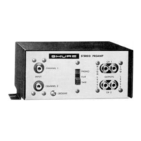
Provides guidance on placement, avoiding hum sources, and connecting grounding wires.

Safety Warning: Transformerless Amplifiers

Warns about shock hazard when used with transformerless (ac-dc) amplifiers and recommends isolation transformers.

Connection and Operation Steps

Details selector switch use, connecting signal leads for Phono/Tape/Flat, and output connections.

Advanced Modifications and Warranty

Balanced Line Output Modification

Describes how to modify the unit for professional low-impedance balanced line use, including gain adjustment.

Full One-Year Warranty

Outlines the warranty coverage, liability limitations, and return procedure for defective units.

Circuit Diagrams and Parts

Model M64 Circuit Diagram

Presents the detailed schematic diagram for the Model M64 stereo preamplifier.

Model M64-2E Circuit Diagram

Presents the detailed schematic diagram for the Model M64-2E stereo preamplifier.

Printed Circuit Board Layout

Shows the physical layout of components on the printed circuit board for reference.

Component Parts List

Lists Shure part numbers and descriptions for components used in the preamplifier assembly.

Related product manuals