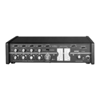
REAR PANEL FEATURES
SCM810 REAR PANEL FIGURE 2
⑪ AC Power Connector and Rocker Switch:
Connector supplies AC power to unit when plugged into a power source: the rocker switch turns the unit on.
⑫ Microphone Logic:
DB-25 male connector interfaces with each channel's GATE OUT, MUTE IN, and OVERRIDE IN logic terminals. See the Suggested Logic Applications section.
NOTE: THIS IS NOT AN RS-232 PORT.
⑬ DIP Switch:
The 7-position DIP switch provides setup options for the mixer (see DIP Switches section).
⑭ LINK IN/OUT Jacks:
Allow multiple mixers to be stacked for additional inputs. Up to 50 SCM810 mixers can be linked.
⑮ LINE OUTPUT Removable Block Connector:
Active balanced line-level signal for connection to amplifiers, recorders or other mixers. Output can be modified to microphone level (see Internal Modifications).
⑯ DIRECT OUT 1/4-inch Phone Jacks:
Provides non-gated aux-level signal from each channel. Direct outs are wired pre-fader and pre-EQ. Can be modified for use as a gated channel output,
send/receive insert point, or external speech gate for mixing consoles (see Internal Modifications section).
⑰ AUX/D.O./D.O. Switch:
Located behind the Line Output connector, this switch selects either aux input function or direct output function for channel 8 Direct Out jack. Left switch position
is AUX IN; center and right positions are DIRECT OUT.
⑱ INPUT 1-8 Removable Block Connectors:
Active balanced microphone- or line-level inputs.
⑲ Input 1 - 8 MIC/PHM/LINE Switch:
Located behind the removable block connector, this switch selects operation at either microphone- level (left), microphone-level with 48 V phantom power
(center), or line-level (right) signals.
DIP Switches
The rear-panel DIP switch provides the following setup options. The positions shown in bold type are the factory settings.
NOTE: Switch positions and effects are shown in Figure 3 and also on the mixer label.
1 2 3 4 5 6 7
(MIXER
REAR
PANEL)
DIP
SWITCH
SW702
MODIFIABLE FUNCTION SWITCHES FIGURE 3
Shure IncorporatedSCM810 Eight-Channel Microphone Mixer
3/132017/10/09
 Loading...