3
FROM
MIC
1
FROM
MIC 2
OUTPUT
1
2
3
1
2
3
1
2
3
ALL RESIST
ORS
232
Ω
, 1%
ISOLATION NETWORK
FIGURE 4
PS1A
POWER SUPPL
Y
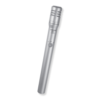
Connect
the microphone cable to the SM81 and the power
supply MICROPHONE connector
. The power supply uses the
balanced
audio cable pair to carry the supply current to the mi
-
crophone, and the cable shield as a ground return.
Connect the power supply OUTPUT connector to a low-
impedance microphone input of the mixer, audio console or
tape recorder. A second SM81 may be connected to the re-
maining power supply channel in a similar manner.
ALTERNATE
POWER SOURCES
As
an alternate to the PS1A
power supply
, the SM81 may
be
phantom powered from virtually any mixer
, audio console or
tape recorder using one of the wiring configurations shown in
Figures
5 and 6. Any well-filtered voltage available in the mixer
from
12 to 48 Vdc may be used. The graph in Figure 7 shows the
range of values which can be used for resistor R when the
SM81
is used with a regulated power supply
. The tolerance of
the resistors (2R) shown in Figure 5 should be 1% or better to
assure close matching, although the absolute value is not
12
3
OUTPUT
TO
MIXER
2R
2R
B+
INPUT FROM
MICROPHONE
TWO-RESISTOR CONFIGURATION
FIGURE 5
12
3
OUTPUT
TO
MIXER
INPUT FROM
MICROPHONE
B+
R
CT
CENTER-TAPPED TRANSFORMER
CONFIGURATION
FIGURE 6
RESISTOR R VALUES
FIGURE 7
critical.
Note that the two-resistor phantom power supply (Fig
-
ure
5) presents a load equal to 4R, paralelled with the mixer in
-
put
impedance, to the SM81.
If the combined parallel load is be
-
low 800 Ω, the transformer configuration (Figure 6) is
recommended,
and if the combined load is 150
Ω
or less, it must
be used.
If the power supply is unregulated, the power supply volt-
age
may drop when the SM81 is connected to
it, due to the add
-
ed
load. T
o account for this load, the value of R may be deter
-
mined as follows. Connect a variable resistance tor resistor
substitution
box) in series with a 10 k
Ω,
10% resistor
. Connect
the
free end of the 10k resistor to ground and the free
end of the
variable
resistor to
B + of the power supply
. Adjust the variable
resistor
until 12 to 36 volts is measured across the 10k resistor
.
Note the actual DC supply voltage and the value
of the variable
resistor. Verify that the resistor value falls within the indicated
range
on the graph of Figure 7. The value of the variable resistor
is the appropriate resistance R for use in Figure 6. If the configu
-
ration
in
Figure 5 is to be used, double the resistor value (2R).
Voltages
as low as 10 Vdc minimum as measured at the micro
-
phone
connector are acceptable. The nominal current drain at
10 Vdc is 1.1 mA. This is the minimum current a power supply
must be able to deliver for properoperation.
For
example, in mixers with 30
Vdc power supplies, the val
-
ue
of 2R for the configuration in Figure 4 could be 3.6 k. T
wo 3.6
k
resistors should be closely matched
(2% or better), and may
be mounted externally with the B+ end connected to the 30 V
terminal. The resistors may also be mounted internally (such
modifications
should be performed by qualified service person
-
nel only).
A
convenient method of battery-powering the SM81 using
two 9 volt batteries is shown in Figure 8. Note that this circuit

 Loading...