14
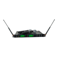
27 pF
20K Ω
27 pF
+5 V
AUDIO
2
1
4
500 Ω
500 Ω
3
2
1
3
4
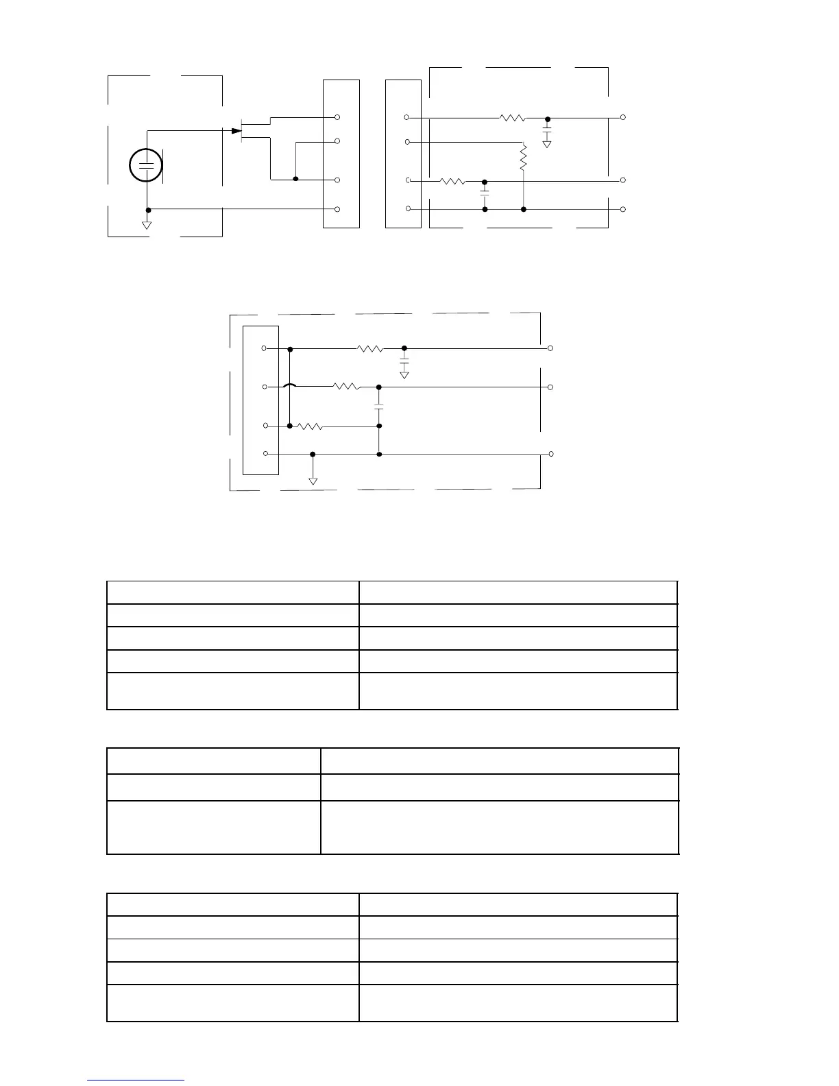
HINWEIS: DAS LAVALIERKABEL VERBINDET Pin 3 UND 4; DAS
GITARRENKABEL ERFÜLLT DIESE FUNKTION NICHT
MIKROPHON
ELEMENT
U1 MIKROPHON–KLINKENPLATTE
ERDUNG
ABSCHIRMUNG
27 pF
499 Ω
499 Ω
3
27 pF
10K Ω
AUDIO
1
4
2
VORSPANNUNG
U1L (LEMO–4 POLIG) MIKROFONBUCHSE
ABBILDUNG 1
U1–Senderausgang
Anschlußtyp: SMC
Tatsächliche Impedanz: 50
Nominaler Ausgangs pegel: +10 dBm
Maximaler Ausgangs pegel: +11 dBm
Pinkonfiguration: Mantel = Erdung
Mitte = Signal
U2–Sendereingang
Eingangskonfiguration: Asymmetrisch, aktiv
Tatsächliche Impedanz: 20 K
MaximaleR Eingangspegel: 3 V
ss
(+0.5 dBV) für 1% Gesamtklirrfaktor bei
minimaler Verstärkungseinstellung und
1–kHz–Signal
U2–Senderausgang
Anschlußtyp: SMC
Tatsächliche Impedanz: 50
Nominaler Ausgangspegel: +10 dBm
Maximaler Ausgangspegel: +11 dBm
Pinkonfiguration: Mantel = Erdung
Mitte = Signal