Do you have a question about the Shure ULX Wireless System and is the answer not in the manual?
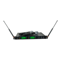
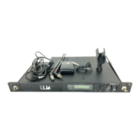
Details ULXS4 Standard and ULXP4 Professional Diversity Receivers.
Bodypack systems offer a choice of lavalier, headworn, or instrument microphones.
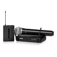
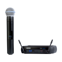
Handheld systems come with a choice of interchangeable microphone heads.
Guitar systems include a 1/4" to mini 4-pin cable for connectivity.
ULXP4 receivers include hardware for rack mounting.
Antenna connectors provide 12 Vdc for active circuit antennas. Use only Shure accessories.
Various coaxial antenna cables like UA802, UA806, UA825, UA850, UA100 are available.
Kit for mounting antennas to the front of a rack.
1/2-wave antenna included with ULXP4 systems.
Inline amplifier for long antenna cable runs.
Kit for mounting antennas to a rack.
Directional antenna for more focused reception.
Combines antennas and power supplies for multiple receivers.
Diagram showing how to rack mount a single ULXP4 receiver.
Diagram showing how to rack mount two ULXP4 receivers.
Rackmount configuration for one receiver using UA506, UA600, UA820.
Rackmount configuration for one receiver using UA440, UA507, UA820.
Rackmount configuration for one receiver using UA844, UA507, UA506.
Rackmount configuration for two receivers using UA844, UA507.
Details power connection and switch for ULXP4 and ULXS4 receivers.
Details power switch and connection for ULX1 and ULX2 transmitters.
Connects using the supplied AC adapter or certified 14-18 Vdc replacement supply.
Illustrates the power switch for ULXP4 and ULXS4 receivers.
Provides typical battery life for 9V alkaline and lithium batteries.
Explains how to use the power/mute switch and lock feature.
Describes the battery power indicator (green/red).
Shows approximate operation time remaining for the transmitter on receiver LCD.
Scans for an open channel within a selected group for single systems.
Illustrates how to change the channel on ULXP4/ULXS4 and ULX1/ULX2.
Illustrates how to change the group on ULXP4/ULXS4 and ULX1/ULX2.
Scans for interference and finds groups with most open channels on ULXP4.
Enables precise frequency selection for large, multiple-system installations.
Steps for maximizing performance by setting multiple systems to different channels.
Indicates wireless activity over the selected channel and signal strength.
Shows which antenna is receiving the strongest signal from the transmitter.
Displays the TV channel occupied by the selected frequency for US models.
Explains squelch function for filtering signals and optimizing range.
Describes XLR and 1/4" audio output connectors and their uses.
Adjusts the level of the receiver's audio outputs.
Guides adjustment of transmitter gain for optimal audio quality.
Details attenuator settings for microphones and guitars.
Explains gain control settings for vocal, loud vocal, and instrument performance.
Indicates when the input signal overloads the transmitter.
Explains how to lock receiver settings to prevent accidental changes.
Details the procedure to unlock receiver settings.
Explains how to lock the transmitter's power state.
Explains how to lock the transmitter's frequency setting.
Addresses common issues like no power, error codes, and no audio.
Provides tips to resolve wireless interference and drop-out issues.
Diagrams for condenser microphone and bodypack transmitter connector wiring.
Diagram for instrument cable wiring.
Details specifications for the ULX1 transmitter.
Details specifications for the ULX2 transmitter.
Details specifications for the ULXS4 and ULXP4 receivers.
Details specifications for audio output configuration and levels.
Details specifications for the receiver's antenna input.
Lists compliance with Canadian ICES-003, EMC, and R&TTE directives.
Details FCC and IC certifications for ULX1, ULX2, ULXS4, ULXP4 models.
Advises users on potential licensing requirements for wireless equipment.
Provides FCC Part 15 compliance information and interference mitigation tips.
Warning regarding proper disposal of used batteries and electronics.
Lists accessories included with the ULX system.
Lists optional accessories for expanding system functionality.
Lists available replacement parts for the ULX system.
Lists frequency ranges for ULX-G3E in European countries.
Lists frequency ranges for ULX R4 in European countries.
Lists frequency ranges for ULX J2 in European countries.
Lists frequency ranges for ULX S3 in European countries.
Lists frequency ranges for ULX-K2E in European countries.
Lists frequency ranges for ULX Q2 in European countries.
Lists frequency ranges for ULX M2 in European countries.
Compatibility guide for frequency band G3E (470-506 MHz).
Compatibility guide for frequency band K2E (606-642 MHz).
Compatibility guide for frequency band X3 (925-932 MHz).
Peru Declaration of Conformity for ULX1-J2 and ULX1-M2 transmitters.
Peru Declaration of Conformity for ULX2-J2 and ULX2-M2 transmitters.
| Modulation | FM |
|---|---|
| Operating Range | 300' (91 m) Line-of-sight |
| Dynamic Range | >100 dB |
| Transmitter Type | Handheld or Bodypack |
| Output Connectors | XLR and 1/4" |