EasyManua.ls Logo

Shure Vocal Master VA 300 User Manual

Shure Vocal Master VA 300
21 pages
To Next Page IconTo Next Page
Page #1 background imageLoading...
Page #1 background image
VA 300
OPERATING AND SERVICE MANUAL
Manufactured by
SHURE BROTHERS INC.
222 Hartrey Avenue
Evanston, Illinois 60204 U. S. A.
Copyright 1978, Shure Brothers Inc.
AL404 (RE) 27A819
Printed in U. S. A.
Question and Answer IconNeed help?

Do you have a question about the Shure Vocal Master VA 300 and is the answer not in the manual?

Shure Vocal Master VA 300 Specifications

General IconGeneral
Power Output100 W
Frequency Response50 Hz - 15 kHz
Impedance8 ohms
Weight68 lb
ComponentsWoofer, Tweeter
Inputs1/4" Jack

Summary

VA300 Specifications

VA300-C Console Specifications

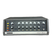
Detailed technical specifications for the VA300-C control console.

VA300-S Speaker Column Specifications

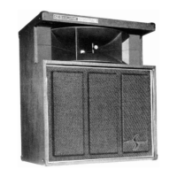
Detailed technical specifications for the VA300-S speaker column.

Controls and Connections

Front Panel Controls Overview

Identification and brief description of front panel controls and indicators.

Rear Panel Controls and Connections

Identification and brief description of rear panel controls and connections.

Operating Instructions

General Operating Instructions

Step-by-step guide for initial setup and basic operation of the VA300 system.

Core Operational Features

Reverberation System Operation

Explanation of the built-in reverb, its controls, and signal mixing.

Service Instructions and Diagrams

VA300-C Functional Diagram

A block diagram illustrating the internal signal flow and components of the VA300-C.

General Service Information

Important notes and warnings regarding servicing the VA300 unit.

Amplifier Component Removal

Procedure for removing the amplifier chassis from its case for servicing.

Front Panel Removal

Procedure for removing the front panel for access to internal components.

Component Level Servicing

Driver Transistor Identification and Replacement

How to identify, handle, and replace driver transistors (Q33, Q34).

Output Transistor Identification and Replacement

How to identify, handle, and replace output transistors (Q35-Q38).

Component Testing and Servicing

Small Signal and Predriver Transistor Servicing

Guidelines for servicing small signal and predriver transistors.

Transistor and Diode Testing Procedures

Methods for testing transistors and diodes using an ohmmeter.

Speaker Column Servicing

Console Replacement Parts List

Circuit Diagram Interpretation

Circuit Diagrams

VA300-C Circuit Diagram

The main schematic diagram for the VA300-C console.

Related product manuals