User’s Manual GC315xx-GC400xx 23
The page E.13(GC315x)/E.14 (GC400x) (MAINTENANCE) displays the counters related to the Genset
maintenance.
In this mode, measures and statuses connected to CANBus PMCBus are displayed.
The page B.01 (MC100/BTB100) displays, for diagnostic purposes, the mains controllers
(MC100) and tie breaker controllers (BTB100) connected to the PMCBus.
The pages B.02, B.03, B.04 (GENSETS) (GC400x) display the information related to the
PMC-Bus mains (PMC-Bus address, active and reactive power) up to 7 gensets.
The page B.05 (PMCB) displays the total nominal power of the gensets (MDPt, kW), the total
active power (kW), the total reactive power (kvar), the total active energy (kWh) and the total
reactive energy (kvarh).
The pages B.06, B.07 (LOAD MANAGEMENT) (GC400x) display the information related to
the load function. This includes the number of network devices, the operating mode of the load
function, the identifier of the pilot generator and the list of priorities.
This mode allows you to access events and data log display.
A number and time&date stamp identifies each record.
The number shows in the top right line of the multifunctional display with the total number of records.
When the archive is full, a new record overwrites the old one; so the identification number may change
in time.
To activate the mode, press the ACK/ENTER button. A menu will guide you to the selection of
the desired function.
6.1
Plus Link
Below are the components of a standard emergency system consisting of a public power line “Mains”,
a “Load” line (the load that you want to feed), a “Generator” line (Generator set with alternator and
drive diesel engine), a control panel containing: a contactor MCB to manage the Mains, a contactor
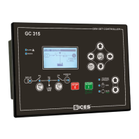
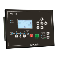
GCB to manage the Generator, a device GC315 or GC315
Plus
to control the engine and the electric
lines concerned, an electronic board to adjust the speed of the engine, a battery trickle charger and a
number of components to manage the auxiliaries (relays, fuses, terminals, etc ...).
The switching of the Load between the Mains and Generator and/or vice-versa, is enabled by
contactors, mechanically and electrically interlocked, fed by the same line but controlled through the
closing and/or opening by the device.
 Loading...