Do you have a question about the Sices GC250 and is the answer not in the manual?
Manual must be kept accessible for quick reference by users.
Users and maintenance personnel must read and understand the manual.
Request replacement copy from manufacturer with device details.
Follow safety rules to avoid accidents during operations.
Indicates symbols used for WARNING and INFORMATION safety messages.
Maintenance by qualified personnel; front panel cleaning with soft cloth.
Recycle old electrical equipment at a special facility.
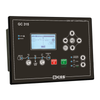
This manual describes the GC250 controller.
Defines BLOCK, DEACTIVATION, and WARNING states of the generator.
Defines MAINS, GENERATOR, LOADS, MCB, GCB circuit breakers, and CANBUS interface.
Defines ISLAND, SPM (Single Prime Mover), and SSB (Single Stand By) applications.
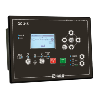
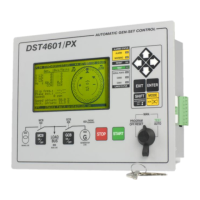
Description of the GC250 front panel, including buttons and indicators.
UP, DOWN, AUTO, START/MANUALE button operations for navigation and mode control.
STOP/OFF-RESET button for engine stop, LAMP TEST, and programming access.
STOP, AUTO, START indicators show operating modes like OFF/RESET, AUTO, MAN.
ALARM and ENGINE RUNNING indicators signal anomalies and engine operational state.
Controls for backlighting, auto-off, and display contrast adjustment.
Methods to scroll through and select display modes like PROGRAM and STATUS.
Layout of the display, divided into top status bar and data area.
Contains mode identifier, page identifier, and current operating mode.
Accessing PROGRAM mode, parameter change warnings, and button function changes.
Managing access codes for parameter programming (Manufacturer, Installer, User).
Procedure for changing parameter values using AUTO, UP, and DOWN buttons.
Steps for editing string parameters using cursor and navigation buttons.
Setting parameters for system protections and alarms, including trip times.
Displaying system status, operating modes, and anomaly alerts.
Monitoring USB and CANBUS communication status and errors.
Viewing controller info, digital input logic, and physical states.
Monitoring digital output logic and physical states.
Viewing analogue input status, voltage, and ohm measurements.
M.01 System, M.02 Mains 1, M.03 Mains 2 pages for system layout and mains data.
M.04 Generator 1, M.05 Generator 2, M.06 Currents, M.07 Powers 1, M.08 Powers 2.
M.09 Energy page for active and reactive energy consumption.
E.01 Engine 1: oil pressure, coolant temp, speed. E.02 Engine 2: battery voltage, fuel level.
E.03 Counters for crank cycles and running hours (clearable and total).
Measurements acquired via CANBUS, dependent on ECU model.
E.11 Maintenance for fuel pump; E.12-15 for exhaust gas treatment.
E.16-21 for customized measurements specific to the ECU.
Navigating to and selecting different types of historical archives.
Details on Events, Fast Analogues, Slow Analogues, and Engine-DTC archives.
Description and components of a standard emergency system with mains and generator.
Description and components of an 'island' system with generator only.
Managing start-up, circuit breaker, and stop sequences based on 'start inhibition'.
Operator control of engine start/stop and load switching via buttons or inputs.
Functionality of Off/Reset mode and primary tasks of Automatic mode.
Sequences for generator start-up on mains failure and load transfer back to mains.
Operator-managed engine start and changeover, or automatic activation.
Using digital inputs for circuit breaker management in manual mode.
Testing generator start-up and operation for emergency preparedness.
Running without load transfer, and automatic mode switch on mains anomaly.
Accessing and modifying date/time via the PROGRAM menu.
Choosing between AUTO and MAN-ON modes for fuel pump management.
Disables the fuel pump; automatically set with fuel pump warning.
Reduces power consumption when genset is stopped, with automatic or manual activation.
| Brand | Sices |
|---|---|
| Model | GC250 |
| Category | Controller |
| Language | English |