Do you have a question about the Sices DST4600A and is the answer not in the manual?
Explains key terms like BLOCK, DEACTIVATION, ALARM, SOFTWARE, and FIRMWARE.
Explains document conventions and validity statements.
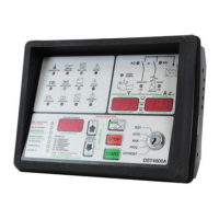
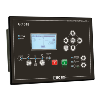
Describes the main area for controls and display on the front panel.
Details the front panel's buttons, key selector, and other control components.
Introduces the different operational modes of the generator set control.
Provides detailed explanations of the OFF/RESET, PROG, MANUAL, AUTOMATIC, and TEST modes.
Lists available data like hours, frequency, voltages, power, pressure, temperature, fuel level.
Details specific display values and system messages shown on the multifunction display.
Explains the meaning of status indicators like KG, KR, ENGINE RUNNING, GENERATOR LIVE, MAINS LIVE.
Explains the V and A displays for voltage and current measurements.
Details power factor, active/reactive power, energy meter, and phase indicators.
Describes fault indicators (TEMPERATURE, LOW OIL PRESSURE, MAX LEVEL) and acknowledgement.
Details other fault indicators like ALARM1, OVERCRANK, NO FUEL, EMERGENCY STOP.
Explains the three categories of faults and their impact on the generator set.
Details how faults are signaled, recognized, and cleared.
Lists and describes specific fault codes (F01-F50) for the generator set.
Details low oil pressure alarms from digital and analogue inputs.
Details high cooling water temperature alarms from digital/analogue inputs.
Describes the starting battery fault condition and visual signal.
Details minimum fuel level alarms from digital/analogue inputs.
Details maximum fuel level alarms from digital/analogue inputs.
Describes the auxiliary alarm condition and visual signal.
Details KR and KG close failure warnings and their conditions.
Describes the max power warning and its conditions.
Explains the deactivation for undervoltage condition.
Explains the deactivation for underfrequency condition.
Describes the emergency stop block condition and visual signal.
Details the manual stop in AUTO mode block condition.
Describes the fuel end block from digital/analogue inputs.
Details low oil pressure block from digital/analogue inputs.
Details high cooling water temperature block from digital/analogue inputs.
Describes non-masked and masked auxiliary block conditions.
Explains the block for overvoltage condition.
Explains the block for overfrequency condition.
Details engine over speed block from digital input or frequency.
Details overload block from digital input or current.
Describes the short circuit block condition.
Details the belt break block condition.
Describes the operating speed not reached block.
Details the OVERCRANK block condition.
Describes the hardware fault block condition.
Details the shutdown failure block condition.
Describes the energy inversion block condition.
Details the inhibition of generator set use block.
Describes the engine not in thresholds when KG closed block.
Describes Lamp Test, Calibration check, and Software level display.
Defines terms used in operating sequences.
Details parameters and states for mains voltage management.
Details parameters and states for generator voltage management.
Defines engine running and dead states.
Explains the conditions for a starting request.
Details the conditions for stop requests.
Describes excitation shutdown and drop-out shutdown systems.
Details the operations when entering MANUAL mode.
Describes the engine starting procedure in MANUAL mode.
Details the engine shutdown procedure in MANUAL mode.
Explains the power change-over process in MANUAL mode.
Describes the initial waiting phase for start requests.
Details the engine starting attempts procedure.
Explains the waiting period for generator readiness.
Details the delay before supplying power to users.
Describes the process of switching users to the generator.
Explains the waiting state when no start requests are present.
Describes the process of switching users back to the mains.
Details the engine cooling phase.
Explains the engine shutdown cycle.
Highlights key differences of TEST mode compared to AUTOMATIC.
Details the power factor measurement and display.
Explains the active power measurement and display.
Details the reactive power measurement and display.
Explains the apparent power measurement and display.
Details the energy meter function and reset.
Provides warnings for connecting TA for power measurement.
Explains how to recover from KR close failure for power availability.
Explains automatic periodical test procedures.
Details the fuel pump control based on fuel level.
Explains how to force generator start using remote test input.
Lists available remote signals for engine and generator status.
Lists further remote signals for speed, generator, and mode status.
Details using OUTPUT 1 for low load status signalling.
Details using OUTPUT 1 for maximum power signalling.
Explains how to view the time and date from the RTC.
Details how to set the time and date for the RTC.
Describes storing time/date into data record databases.
Explains RTC-based and standard periodical test modes.
Describes the function to enable/disable generator based on time/day.
Explains the difference in ALARM2 input function.
Details the difference in KR management.
Explains KG management differences in test operation.
Details differences in 'MAINS SIMULATION' delay time.
Explains differences in generator frequency/voltage usage.
Details the difference in Terminal 8 function.
Explains the difference in Terminal 10 function.
Details the specific alarm for asynchronous engines.
Lists the SMS protocol document.
Lists the DTS4600-PC communication protocol document.
Lists the ModBus protocol document.
Lists the remote signal operating manual document.
| Mounting | Panel mount |
|---|---|
| Operating temperature | -20°C to 70°C |
| Storage temperature | -30°C to 80°C |
| Input | Digital and analog inputs |
| Output | Relay outputs |
| Control Algorithm | PID |
| Resolution | 0.1 |