ii User’s Manual
1 General Information ..................................................................................................... 5
1.1 Definitions ............................................................................................................. 5
1.2 Symbols ................................................................................................................ 5
1.3 Document validity ................................................................................................. 5
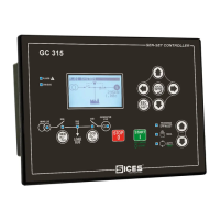
2 Front Panel .................................................................................................................... 6
2.1 Operating and Functions Controls Area................................................................ 7
2.1.1 Operating area ............................................................................................... 7
2.1.2 Functions Area ............................................................................................... 9
2.1.3 Operating Conditions and Measurements Area ............................................ 11
2.1.4 Faults Area ................................................................................................... 12
3 Start Initialization ........................................................................................................ 14
4 Faults ........................................................................................................................... 14
4.1 List of Fxx Codes ................................................................................................ 15
4.2 Alarms ................................................................................................................ 16
4.2.1 Low oil pressure ........................................................................................... 16
4.2.1.1 From digital input .................................................................................. 16
4.2.1.2 From Analogue Input ............................................................................ 16
4.2.2 High Cooling Water Temperature ................................................................. 16
4.2.2.1 From Digital Input ................................................................................. 16
4.2.2.2 From Analogue Input ............................................................................ 16
4.2.3 Starting Battery Fault .................................................................................... 17
4.2.4 Minimum Fuel Level in the Tank ................................................................... 17
4.2.4.1 From Digital Input ................................................................................. 17
4.2.4.2 From Analogue Input ............................................................................ 17
4.2.5 Maximum Fuel Level in the Tank .................................................................. 17
4.2.5.1 From Digital Input ................................................................................. 17
4.2.5.2 From Analogue Input ............................................................................ 17
4.2.6 Auxiliary Alarm ............................................................................................. 18
4.2.7 KR close failure ............................................................................................ 18
4.2.8 KG close failure ............................................................................................ 18
4.2.9 Max power .................................................................................................... 18
4.3 Deactivations ...................................................................................................... 19
4.3.1 Generator’s Voltage Under Minimum Threshold (“UNDERVOLTAGE”) ....... 19
4.3.2 Generator’s Frequency Under the Minimum Threshold
(“UNDERFREQUENCY”) ......................................................................................... 19
4.4 Blocks ................................................................................................................. 19
4.4.1 Emergency STOP ........................................................................................ 19
4.4.2 Manual Stop in AUTO .................................................................................. 20
4.4.3 Fuel END ...................................................................................................... 20
4.4.3.1 Digital input ........................................................................................... 20
4.4.3.2 From Analogue Input ............................................................................ 20
4.4.4 Low Oil Pressure .......................................................................................... 20
4.4.4.1 From Digital Input ................................................................................. 20
4.4.4.2 From Analogue Input ............................................................................ 20
4.4.5 High Cooling Water Temperature ................................................................. 21
 Loading...