Operating Instructions Chapter 3
ICR880/890
Product description
8011325/XL85/2013-08-20 © SICK AG · Germany · All rights reserved · Subject to change without notice 17
3 Product description
This chapter describes the design, the features and the functions of the Camera System.
For installation, electrical installation and startup assistance as well as system config-
uration using the SOPAS-ET Configuration Software, please read this chapter prior to
carrying out any of the tasks.
3.1 Design of the Camera System
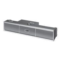
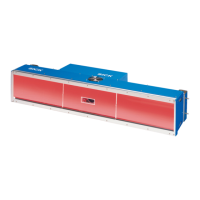
The Camera System consists of the ICD880 or ICD890 Camera (Image Capture Device), the
ICI890 Illumination (Image Capture Illumination) and an optional deflection mirror. The
Camera System is operated in combination with the MSC800 (Modular System Controller)
via a CAN bus. The MSC800 supplies the Camera System with power.
For further information on the MSC800, see the MSC800 Operating Instructions (part
no. 8011540).
External sensors are required for the reading pulse, detection of the object distance and for
creation of the increment signal. These sensors and the superordinate host processor are
connected to the MSC800.
Fig. 3-1: ICR880/890 Camera System in combination with the MSC800 (single-side reading)
MSC800
Power supply
Mains connection
ICR880/890 System
CAN bus
HOST
Reading pulse
Conveyor speed
MLG Light Grid/
VMS4xx/5xx
Object distance/
Object geometry
 Loading...