Operating Instructions Chapter 3
ICR880/890
Product description
8011325/XL85/2013-08-20 © SICK AG · Germany · All rights reserved · Subject to change without notice 19
3.1.2 Included in delivery
Delivery of the ICR880/890 Camera System includes the following components:
Important For save operation of the SD memory card, use only SICK approved memory card.
An overview of cleaning agents for the front window of the illumination is available in Chap-
ter 10.3, Page 92.
Piece(s) Components Comment
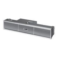
1 Camera with SD memory card ICD880 or ICD890, depending on order
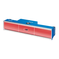
1 ICI890 Illumination Type-depending
1 Deflection mirror (optional) Type-depending
1 MSC800 Type-depending, without connection
cables
1 MLG Light Grid (pre-configured) height dis-
tance detector with connection cable and
installation kit
Application-specific
– or –
1 Object distance detector VMS4xx/5xx with
connection cables and installation kit
4 180° brackets with installation accessories For Camera System and deflection mirror
1 WL18-3 Reading Pulse Sensor (pulse photo-
electric reflex switch) with connection cable
and installation kit
Triggering the reading procedure
1 Connection cable For the power supply of the Camera Sys-
tem
1 Connection cable For the power supply of the ICI890 Illumi-
nation via the camera
1 Connection cable For control of the ICI890 Illumination via
the camera
1 CAN bus data link For networking the Camera System with
MSC800 via the CAN bus
1 Terminal resistance For CAN bus termination at the Camera
System
1 Incremental encoder, resolution
10 mm (394 mil)/pulse
Optional (application-specific)
– or –
1 Incremental encoder, resolution
0.2 mm (7.9 mil)/pulse (using VMS4xx/5xx)
Installation frames Optional (application-specific)
1 Notes on Device with electrical connection
diagram as primary information
Included in the device packaging of the
Camera System
Tab. 3-1: Included in the delivery of the ICR880/890 Camera System
 Loading...