Operating Instructions Chapter 3
ICR880/890
Product description
8011325/XL85/2013-08-20 © SICK AG · Germany · All rights reserved · Subject to change without notice 21
3.2 System requirements
3.2.1 Installation requirements
Typical space requirements above the highest object (for reading from above): applica-
tion-specific
Unobstructed view of the objects for the Camera System
Stable installation frames with sufficient load capacity and measurements suited to the
Camera System (see Chapter 9.5 ICR880/890 Camera System dimensional drawing,
Page 86 )
Four 180° brackets for the Camera System/the deflection mirror (included in delivery)
Shock absorbent and vibration free attachment
Important An installation frame made of 80 mm (3.15 in) item aluminium profiles can be used for sim-
ple system installation (Fig. 3-3). The 180° brackets are aligned to these profiles.
3.2.2 Electrical installation requirements
Power supply (via MSC800): 100 V to 264 V AC/50 Hz to 60 Hz
Reading pulse sensor (start/stop), e.g. photoelectric reflex switch (included in delivery):
For detecting an object with external reading pulse
Additional appropriate reading pulse sensor (stop), e.g. photoelectric reflex switch: For
detecting the end of pulse with extended external reading pulse
Pre-configured MLG Light Grid (included in delivery): when reading from above to detect
the object distance
VMS4xx/5xx Volume Measurement System: when reading from the side or for multi-
side reading to detect the object distance
Suitable incremental encoder, e.g. part no. 2058477 (resolution 10 mm (394 mil)/
pulse). Device is included in delivery depending on the system configuration
Host computer with RS 232, RS 422/485, Ethernet or PROFIBUS-DP data interface:
For further processing of the reading data via MSC800
Suitable visualization PC or PLC: To display the system status
Connection cables: See Chapter 5.3.4, Page 51
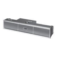
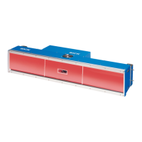
Fig. 3-3: Example of simple Camera System installation on the installation frame
 Loading...