Operating Instructions Chapter 3
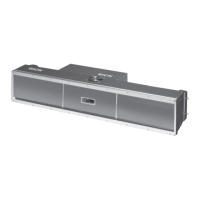
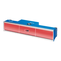
ICR880/890
Product description
8011325/XL85/2013-08-20 © SICK AG · Germany · All rights reserved · Subject to change without notice 23
3.3 Product features and functions (overview)
Feature Characteristics
ICD880/890 Camera CMOS line with 8,192 pixels (standard device)
Dynamic focus setting
ICD880: lens with focal point distance 80 mm (3.15 in),
ICD890: lens with focal point distance 135 mm (5.32 in)
Type-depending reading ranges (z.B. standard device ICD890: 1.4 m to 3.0 m (4.59 to 9.84 ft))
Type-depending image resolution (e.g. standard device ICD890: 170 to 350 dpi)
Scanning frequency max. 19.1 kHz (standard device)/max. 30 kHz (high speed device)
Can be adapted to the print quality of the code
Analysis area of the CMOS line can be restricted
Real time image output (grey values: "*.jpg", "*.tif")
User safety and
convenience
Robust, compact metal housing, enclosure rating max. IP 64, CE mark
Laser class 1M, switching off the LED ICI890 Illumination in case of prolonged active reading gate or if
the output capacity is exceeded, minimum power on-time 3 s
Automatic self-test on system startup
Diagnosis tools for system setup and system (distance) monitoring
Configurable reading diagnosis data display in two reading result formats
Operational data retrieval, error code display on request in case of errors
Activatable test string function for signalling readiness for operation
Password protected configuration mode
Back up of configuration parameter values (cloning) also on SD memory card
(can be removed when replacing the camera)
Future proof due to firmware update (flash PROM) via data interface
Future proof SOPAS-ET Configuration Software
Extended power supply voltage range
Necessary maintenance or service task displayed via LED and system report
The camera or illumination can be replaced within 10 min
Convenient configuration Configuration (online/offline) and display of image memory contents via the SOPAS-ET Configuration
Software (incl. help system)
Status indicators via five LEDs
Operating modes Configuration mode
Reading operation
Reading operation mode Object tracking (max. 10 objects per second, minimum gap 50 mm (1.97 in))
Reading pulse External reading pulse via MSC800
1D/2D code detection Data Matrix ECC200, PDF417, Maxicode, QR cdoe / all conventional bar codes
Max. number of 1D codes: 50 per reading pulse
Max. number of 2D codes: 10 per reading pulse
Separation of identical codes of the same code type using the code position
Output sorting: Code position, FIFO, LIFO, code lengths list
Manipulation of output strings via filter or format masks
Data communication Main data interface HOST (via MSC800):
AUX auxiliary data interface: Fixed output format with special diagnosis functions, communication via
RS 232 or Ethernet interface, application for configuration/diagnosis
Two 1 GBit Ethernet interfaces for fast image output
Electrical interface AUX data interface: RS 232 serial, Ethernet or CAN (fixed transfer rate, data format and protocol)
CAN interface for integration into SICK CAN-SENSOR Network with the MSC800
Ethernet interface (10/100 MBps), TCP/IP and FTP
Two 1 GBit Ethernet interfaces, FTP
Connection to PROFIBUS-DP via MSC800
Connection technology
(design)
Data and function interfaces: M12 connector for industrial use
GBit Ethernet: Phoenix VARIOSUB RJ-45 sockets, enclosure rating IP 67
Power supply: Harting plug-in connectors
Tab. 3-4: Product features and functions of the ICR880/890 Camera System (overview)
 Loading...