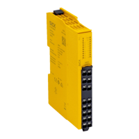
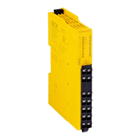
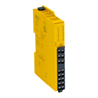
3.2.3 Compatible sensor types
The safety relay is suitable for:
•
S
afety sensors and safety switches with volt-free output contacts, e.g.: Dual-chan‐
nel safety command devices (emergency stop pushbuttons, rope pull switches,
etc.), dual-channel contact-based interlocking devices (safety locking devices and
safety switches) and dual-channel magnetic safety switches with reed contacts
3.2.4 Restart interlock
A restart interlock can be implemented with a reset pushbutton.
3.2.5 External device monitoring
Permanent external device monitoring can be implemented using external wiring.
3.2.6 Cross-circuit detection
A cross-circuit is detected on the safety capable inputs.
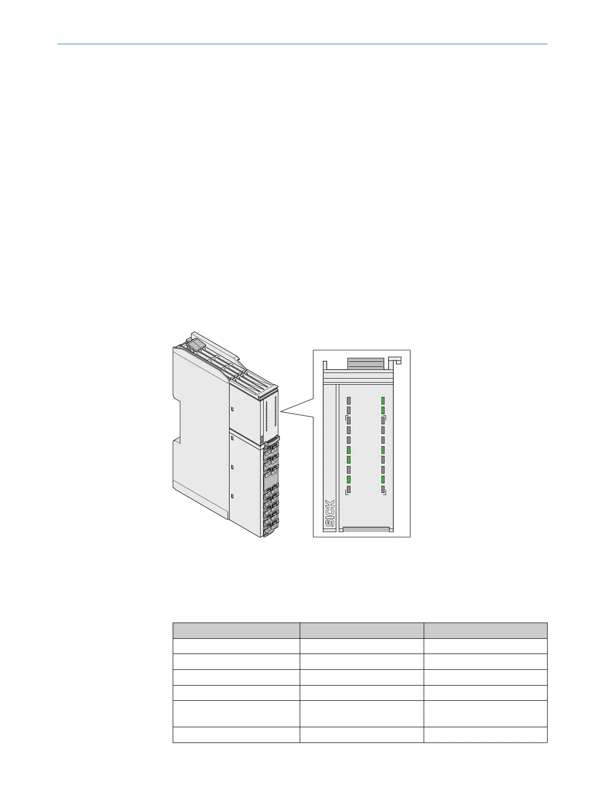
3.2.7 Status indicators
LEDs
RELY
PWR
OUT
1
3
2
3
I1
Y1
14
2
4
I2
Y2
A2
S1
3
3
A1
R1
34
X1
X2
PWR
OUT
13
23
I1
Y1
14
24
I2
Y2
A2
R1
A1
S1
X1 X2
EMSS3
1099973
RELY
33 34
Figure 2: LEDs
The labeled positions are only partially assigned LEDs. The positions and their labeling
(e
xcept for the upper 2 lines) also show the pin assignment of the terminals on the front
connector.
Table 1: Safety relay indicators
Labeling Color Function
PWR Green/Red Voltage supply
OUT Green Enabling current paths
I1 Green Safety capable input
I2 Green Safety capable input
S1 Green Reset pushbutton input, exter‐
nal de
vice monitoring (EDM)
Y1 Green Application diagnostic output
3 PRODUCT DESCRIPTION
10
O P E R A T I N G I N S T R U C T I O N S | ReLy EMSS3 8023937/2019-10-11 | SICK
Subject to change without notice