Do you have a question about the Side-Power PJC 221 and is the answer not in the manual?
Covers installer's role, safety laws, and regulatory compliance.
Details warranty voiding for faulty installations and S-link product integration rules.
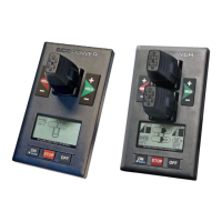
Describes the layout, buttons, and display of the PJC-221 control panel.
Describes the layout, buttons, and display of the PJC-222 control panel.
Details input voltage, current, operating temperature, and panel dimensions.
Illustrates connections for optional external buzzer and power supply.
Guides through initial system setup, including conflict resolution and auto-configuration.
Explains how to navigate the system menu using the joystick and buttons.
Details viewing and configuring connected S-link devices and their properties.
Explains the function of setup buttons for navigation, editing, and saving parameters.
Covers bow/stern direction, pump control, and cooling settings for PHC 024.
Details cooling power save, tank monitor, thruster, and instance settings for PHC 024.
Covers bow/stern direction and other setup parameters for the PHC-3 controller.
Sets the location and direction for the PDC 101 AC thruster controller.
Sets the location and direction for the PDC 201 AC thruster controller.
Details location, direction, function, and max output for the PDC 301 controller.
Sets the location for the automatic main switch in the DC system.
Covers location, direction, function, and output settings for PPC/SR controllers.
Sets the amount of thrust for RCRS 1 and RCRS 2 thrusters.
Configures MSI8730 location and sets the thrust percentage.
Displays firmware version and serial number for ESI and GW devices.
Calibrates the HOLD function for balanced thruster thrust.
Calibrates the joysticks for accurate control input.
Describes accessing and displaying system information via the menu.
Details information displayed for PPC, SR150000, and SR61242 devices.
Displays motor speed, power, temp, and thrust for AC thruster controllers.
Shows oil pressure, temp, thrust, firmware, and serial number for hydraulic controllers.
Details panel firmware, hardware, serial number, and system voltage.
Monitors S-link bus error status and communication quality.
Configures backlight level, night color, and timer auto-off for the panel.
Sets warnings for retract operations and relay output levels.
Adjusts display and joystick orientation based on panel placement.
Explains how alarms are shown on the panel and the basic indicators used.
Covers auto reset, specific alarms, and procedures for silencing alarms.
Describes Reduced Power Mode and Power Not Available status.
Shows examples of display views for various thruster configurations and panels.
Explains symbols for DC thrusters including battery and temperature indicators.
Explains symbols for AC thrusters including motor temperature indicators.
Explains symbols for hydraulic thrusters including oil temperature indicators.
Explains symbols for thruster deployment, retraction, and status.
Describes how thrust power and direction are displayed for bow/stern thrusters.
Explains the HOLD function for auto-running thrusters together.
Details how to calibrate the HOLD function for balanced thruster output.
Lists warning signals related to the HOLD function based on voltage and temperature.
Describes how to change the system language from the main menu.
Explains how to reset all system parameters to factory default settings.
How to turn the stabilizer system ON/OFF and AnySpeed ON/OFF.
Lists common error codes, their descriptions, and recommended actions.
Continues the list of alarm codes, descriptions, and actions for various faults.
Detailed list of fault codes, causes, and actions for the PHC-3 hydraulic system.
Further PHC-3 faults including ECI pump and VFD issues with their actions.
Describes faults related to VFD communication for the PDC-301 controller.
A dedicated page for user notes and annotations.
Template for recording S-link device type, location, and serial numbers.
| Brand | Side-Power |
|---|---|
| Model | PJC 221 |
| Category | Control Panel |
| Language | English |