Do you have a question about the Siemens 3VA1 100 A and is the answer not in the manual?
Provides overview of 3VA molded case circuit breakers, their benefits, and the scope of the manual.
Details technical support and reference documents related to the 3VA product line.
Provides an overview of 3VA molded case circuit breakers, their applications, and product portfolio.
Details the integrated 3VA portfolio of molded case circuit breakers in different rated operational current versions.
Highlights key features like compact design, various pole versions, and thermal-magnetic trip units.
Focuses on features like increased breaking capacity, selective protection, and electronic trip units.
Explains the functions of Electronic Trip Units (ETUs) for protection, including overload and short-circuit protection.
Illustrates practical applications of 3VA molded case circuit breakers in various scenarios.
Describes specific applications for 3VA1 and 3VA2 breakers, including line, generator, and residual current protection.
Presents detailed technical specifications for 3VA1 and 3VA2 breakers, including breaking capacity and trip units.
Shows compatibility between accessories and different 3VA breaker sizes and series.
Discusses the integrated system approach for 3VA breakers and accessories, emphasizing standardized operation.
Explains how to choose the right circuit breaker and components for various installation locations.
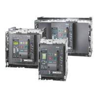
Details fixed mounted, plug-in, and draw-out installation variants available for 3VA molded case circuit breakers.
Illustrates color-coded switching positions in the draw-out unit for easy identification.
Focuses on ergonomic features like handles, status indications, and illumination kits.
Explains how control elements are color-coded to signify specific functions for quick setting.
Discusses internal accessories, their family design, and color coding for easy installation.
Describes the available connection systems for 3VA circuit breakers and their integration.
Details various cable types and busbar materials compatible with 3VA circuit breakers.
Explains how to identify circuit breakers using labels and plates attached to the unit.
Details the information displayed on the front panel, including approvals and trip unit type.
Explains how to open, close, and reclose circuit breaker contacts using the manual operator.
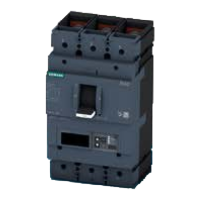
Illustrates the design and components of the 3VA1 molded case circuit breaker.
Illustrates the design and components of the 3VA2 molded case circuit breaker.
Defines current limitation and explains its benefits, including reduced thermal load and dynamic forces.
Defines rated ultimate short-circuit breaking capacity (Icu) and available classes.
Explains how selectivity ensures only the closest upstream device trips during a fault.
Details factors influencing selective behavior of breakers, like trip unit settings and times.
Explains ZSI for controlling total breaking time in series-connected breakers.
Highlights 3VA2's excellent selective tripping, current limiting, and breaking capacity features.
Summarizes standards and guidelines that 3VA molded case circuit breakers comply with.
Lists specific IEC/EN standards that 3VA molded case circuit breakers fulfill.
Details EMC standards and resistance to electromagnetic factors like waves and surges.
Covers pollution degree and ambient temperature ranges for operation and storage.
Illustrates the permissible mounting positions for 3VA molded case circuit breakers.
Explains safety clearances required for short-circuit interruption and lists their purposes.
Provides tables with minimum clearances for 3VA1 breakers based on voltage and accessories.
Provides tables with minimum clearances for 3VA2 breakers based on voltage and accessories.
Explains protection functions defined by trip unit choice (thermal-magnetic vs. electronic).
Explains how to dimension protection settings based on tripping characteristics for thermal-magnetic and electronic trip units.
Discusses supplementary conditions and introduces SIMARIS design software for network calculation.
Explains overload protection (L) characteristics and the role of thermal image.
Explains the S function for time-selective short-circuit tripping in networks.
Describes the instantaneous short-circuit protection function responding to exceeding tripping current.
Details G protection for detecting residual currents and responding to ground fault current.
Explains N protection for the neutral conductor against overloads and short circuits.
Describes ZSI for controlling total breaking time in series-connected breakers.
Provides a table indicating accessory compatibility with different 3VA breaker sizes and series.
Illustrates combinability of different accessories using tables and examples.
Lists the portfolio of internal accessories including switches, releases, and communication modules.
Shows mounting locations for internal accessories on 3VA1 breakers based on size and pole number.
Details auxiliary and alarm switches, their installation, and types (HQ, HP).
Explains auxiliary releases for remote tripping, monitoring control/main circuits, and easy installation.
Lists detailed technical specifications for HQ, HQ el, and HP switches.
Contains information and a description of the 3VA connection system for connecting cables/busbars safely.
Illustrates components for direct cable connection at the front of the circuit breaker.
Describes the box terminal, its selection as an alternative to lug terminals, and cable/busbar compatibility.
Illustrates components for busbar or cable lug connections on the front panel.
Illustrates components for busbar or cable lug connections on the rear panel.
Mentions optional insulating equipment for termination areas and auxiliary conductor terminals.
Explains phase barriers for insulation between phases and their compatibility with other accessories.
Details terminal covers providing IP40/IP20 protection, with markings for voltage detector bore.
Introduces plug-in and draw-out units for applications requiring quick replacement and functional expansion.
Describes plug-in technology as less expensive, space-saving, with keyed, friction-locked connections.
Explains draw-out versions with plug-in contacts, side walls, guide mechanism, and crank handle for operation.
Discusses auxiliary circuit connectors for quick disconnection in plug-in/draw-out units, noting different versions.
Explains position signaling switches for signaling 'Plug-in unit - MCCB correctly bolted'.
Lists benefits like quick replacement, clear isolation evidence, remote signaling, and locking.
Details draw-out versions for applications needing regular inspections and safe electrical isolation.
Explains CONNECT, TEST, and DISCON positions, and the UNBLOCK state for draw-out units.
Lists components for converting to draw-out version, including socket, contacts, and plunger.
Explains the autotrip plunger's safety functions and proper installation requirement.
Explains using padlocks through plastic frame opening for the draw-out socket.
Describes retrofitting a cylinder lock for locking draw-out units in CONNECT, TEST, or DISCON positions.
Lists available manual operators: front mounted, door mounted, and side wall mounted rotary operators.
Explains how to open and close the circuit breaker using the manual operator.
Describes front mounted rotary operators, available with or without door interlock.
Describes door mounted rotary operators allowing operation through the cubicle door without opening it.
Describes side wall mounted operators allowing operation through cubicle side walls.
Outlines locking by handle, rotary operator, and mutual interlocking by Bowden cables.
Explains how to lock front, door, and side wall mounted rotary operators by the handle.
Details locking/interlocking by rotary operator using padlocks or cylinder locks.
Explains using Bowden cables for mutual interlock between up to three breakers, blocking handles.
Lists IP degrees of protection for different operators, including front mounted with escutcheon.
Introduces the MO320 motor operator for opening/closing breakers via electrical control cables.
Explains MANUAL, AUTO, and LOCK modes for the MO320 motor operator.
Guides on closing and opening the 3VA breaker using manual mode.
Lists common faults, their causes, and remedial actions for the MO320 motor operator.
Lists technical specifications for the MO320 motor operator, including ambient temperature and power supply.
Outlines the distinction between locking and interlocking of 3VA molded case circuit breakers.
Explains how padlock devices can lock breakers in OFF or ON positions, preventing operation.
Explains how interlocking devices implement mutual interlocks between breakers, releasing one at a time.
Describes the padlock device attached directly to the handle for locking in the OFF position.
Explains fitting cylinder locks (type Ronis) for locking breakers in OFF/ON positions.
Explains front interlocks installed on the breaker panel for interlocking multiple breakers.
Details using Ronis cylinder locks for mutual interlocks, ensuring only one breaker is ON at a time.
Explains Bowden cable interlock for up to three breakers, blocking handles via sliding bar modules.
Describes sliding bar for interlock between three breakers, allowing padlock locking of the slide.
Explains the rear interlock system operating via a tappet engaging the breaker mechanism from the rear.
Emphasizes referring to documentation and using qualified personnel for servicing and maintenance.
Specifies recommended inspection intervals (annual, after 1000 trips, or twice yearly for harsh atmospheres).
Provides recommended inspection steps for MCCBs, including checking connections, surfaces, and protection parameters.
Outlines optional inspection procedures for ETU of 3VA2 breakers, testing protective functions and metering.
Explains identifying and rectifying trip causes before re-switching on the breaker.
Covers troubleshooting common problems like repeated tripping, incorrect switching, and faults during automatic reset.
Illustrates circuit diagrams for basic units, with thermal-magnetic trip units, and different pole configurations.
Illustrates contact diagrams for AUX, TAS, EAS switches and position signaling switches.
Shows circuit diagrams for undervoltage releases, universal release, and shunt trip.
Details circuit diagrams for front mounted motor operators and actuation via control cable.
Illustrates circuits to prevent no-load operation using auxiliary contactors and undervoltage release.
Illustrates circuit diagrams for plug-in and draw-out units with optional position signaling switches.
Shows circuit diagrams for basic 3VA2 units, fixed mounting and plug-in/draw-out, 3/4-pole.
Illustrates circuit diagram for 3-pole 3VA2 breaker in 5-wire system with external current transformer.
Shows circuit diagrams for auxiliary switches, alarm switches, and position signaling contacts.
Shows circuit diagram for loadside RCD advanced (RCD820), 3/4-pole.
Illustrates T-Connector and COM800/COM100 breaker data server, mentioning optional bus terminating resistor.
Shows diagrams for COM800/COM100 with PROFIBUS DP and PROFINET expansion modules.
Illustrates the circuit diagram for the EFB300 external function box.
Shows circuit diagrams for N conductor current transformer and manual handle illumination kit.
Illustrates the circuit diagram for time-delay devices for undervoltage releases.
Shows a circuit diagram example of a 3VA2 MCCB with built-on/built-in accessories.
Illustrates an EMERGENCY-STOP circuit with 3VA breaker and UVR (LNO) release.
Shows circuit diagrams for electrical interlocking of two MCCBs using undervoltage releases.
Provides dimensional drawings for basic units of 3VA10, 3VA11, 3VA12, 3VA20, 3VA21, 3VA22 series.
Shows dimensional drawings for 3VA10/3VA11 breakers in 1, 2, 3, and 4-pole configurations.
Provides dimensional drawings for 3VA12 250 A, 3-pole and 4-pole MCCBs.
Shows dimensional drawings for 3VA20/3VA21/3VA22 series, 3-pole MCCBs.
Provides dimensional drawings for 3VA20/21/22 series, 4-pole MCCBs.
Shows dimensional drawings for 3VA23/3VA24 series, 3-pole and 4-pole MCCBs.
Provides dimensions for various accessories including connection technology and phase barriers.
Shows dimensions for rear busbar and cable lug connections for plug-in and draw-out units.
Provides dimensions for rear connecting studs used for busbars and cable lugs.
Shows dimensional drawings for phase barriers used for insulation between phases.
Provides dimensions for extended terminal covers, detailing A, B, C measurements.
Provides dimensional drawings for broadened terminal covers, detailing A, B, C measurements.
Shows dimensional drawings for insulating plates, detailing A, B, C, D measurements.
Provides dimensional drawings for broadened insulating plates, detailing A, B, C, D measurements.
Shows dimensional drawings for plug-in sockets, detailing A-L measurements.
Provides dimensional drawings for draw-out units, detailing A-P measurements.
Shows dimensional drawings for door feedthroughs, detailing A, B, C, D measurements.
Provides dimensional drawings for front mounted rotary operators, detailing A-G measurements.
Shows dimensional drawings for door mounted rotary operators, detailing A-C measurements.
Provides dimensional drawings for side wall mounted rotary operators, detailing A-E measurements.
Details dimensional drawings for rotary operators with shaft stub, A-H measurements.
Shows dimensional drawings for MO320 motor operator, detailing A-F measurements.
Illustrates dimensional drawings for padlock devices for handles and cylinder locks.
Provides dimensional drawings for sliding bars with Bowden cable, detailing A-D measurements.
Shows diagrams for rear interlocks for plug-in/draw-out units, including dimensions.
Shows dimensions for RCD310/RCD510 with 3-pole 3VA1 MCCB size 160 A.
Shows dimensions for RCD320/RCD520 with 3VA1 MCCB size 160 A.
Introduces COM800 and COM100 breaker data servers for system integration.
Provides dimensional drawings for DSP800 display.
Shows dimensional drawings for EFB300 external function box.
Lists international standards to which 3VA1 and 3VA2 breakers conform.
Explains ESD components and how they are destroyed by voltage below human perception.
Illustrates required ESD protective measures and work center setup.
Provides a summary of abbreviations used in the document, starting with AC, ACT, AL, ASCII.
Provides a table for converting AWG/kcmil to mm2 and metric equivalents.
Lists conversion factors for units of length and weight.
Provides temperature conversion factors between Celsius and Fahrenheit.
Defines AUTO mode for remote operation of motor operators via control cables.
Defines making capacity and its expression for MCCBs.
Defines MANUAL as local, manual operating mode for motor operators.
Explains protective characteristic determined by rated operational current and trip values.
Defines rated breaking capacity as the maximum interruptible current.
Defines rated making capacity as maximum closing current by utilization category.
Defines rated operational current (In) for MCCBs, equivalent to uninterrupted and thermal current.
Defines peak withstand current as maximum instantaneous short-circuit current.
Defines rated residual current (IΔn) for which RCDs are designed.
Defines Ics as interruptible current, allowing repeated tripping after a short circuit.
Defines Icn as maximum safely interruptible current at rated voltage/frequency.
Defines Icm as maximum interruptible current at closing, and mentions factor n.
Defines current value at which a trip unit trips within a specified time.
Defines the limit value for ground fault current that triggers protection.
Defines current limit exceeding which the breaker trips instantaneously.
| Brand | Siemens |
|---|---|
| Model | 3VA1 100 A |
| Category | Power Tool |
| Language | English |