Do you have a question about the Siemens 3VA2 160 A and is the answer not in the manual?
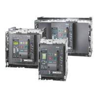
Provides an overview of 3VA portfolio and application areas.
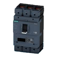
Overviews ergonomic design features of 3VA molded case circuit breakers.
Summarizes technical features of 3VA molded case circuit breakers.
Lists factors influencing selective behavior of circuit breakers.
Explains current selectivity based on time-current characteristics.
Describes achieving selectivity through time-based tripping.
Explains ZSI for controlling breaking time in series-connected breakers.
Details dynamic selectivity based on arc power evaluation.
Defines full selectivity in power systems.
Explains partial selectivity based on ultimate selectivity value.
Discusses selective tripping with 3VA2 breakers.
Lists standards fulfilled by 3VA molded case circuit breakers.
Details EMC requirements and resistance factors.
Covers pollution degree and ambient temperature limits.
Illustrates permissible mounting positions for 3VA breakers.
Specifies safety clearances required between components.
Explains degrees of protection (IP) as defined by standards.
Explains protection functions based on trip unit choice.
Describes tripping characteristics for thermal-magnetic and electronic trip units.
Guides on setting tripping characteristics and using SIMARIS design.
Details overload protection (L) and thermal image functions.
Explains short-time delayed short-circuit protection (S).
Describes instantaneous short-circuit protection (I).
Explains ground-fault protection (G).
Details neutral conductor protection (N) and its application.
Explains the components of a thermal-magnetic trip unit.
Explains the concepts behind electronic trip units.
Lists protection functions available for different ETU types.
Explains the operator controls for ETU types.
Explains load management functions for ETU 3-series.
Details main applications for 3VA breakers as line protection components.
Identifies suitable breakers and trip units for line protection.
Explains derating for thermal-magnetic trip units.
Lists ETUs suitable for line protection applications.
Details parameters for the ETU320 LI.
Details parameters for the ETU330 LIG.
Details parameters for the ETU350 LSI.
Covers parameter input and additional features of 5/8-series ETUs.
Details functions and parameters for ETU550/ETU850 LSI.
Details functions and parameters for ETU560/ETU860 LSIG.
Lists parameters for 3-pole ETU560/ETU860.
Lists parameters for 4-pole ETU560/ETU860.
Explains the deployment and features of 3VA1 switch disconnectors.
Describes the isolating function and symbol compliance.
Defines rated making and breaking capacity.
Covers DC network applications and specific features.
Provides breaking capacity data for DC applications.
Details applications of 3VA breakers in 400 Hz networks.
Explains IT system applications and selection criteria.
Describes critical fault situations in ungrounded IT systems.
Introduces the range of accessories available for 3VA breakers.
Details internal accessories and their mounting locations.
Describes auxiliary and alarm switches, including HQ and HP versions.
Provides technical specifications for auxiliary and alarm switches.
Details the 3VA connection system, including cables and busbars.
Lists the portfolio of connection components for 3VA breakers.
Illustrates components for direct cable connection at the breaker.
Details box terminal types and sizes for cable and busbar connection.
Illustrates components for busbar or cable lug connection on the front panel.
Explains connecting busbars and cable lugs directly to jumper lugs.
Details front connection bars for connecting larger busbars and cable lugs.
Describes front connection bars for connecting very large busbars and cable lugs.
Explains front connection bars for connecting large busbars and cable lugs.
Illustrates components for busbar or cable lug connection on the rear panel.
Explains the ZSI function for controlling total breaking time.
Shows circuit diagrams for various auxiliary releases.
| Brand | Siemens |
|---|---|
| Model | 3VA2 160 A |
| Category | Power Tool |
| Language | English |