EasyManua.ls Logo

Siemens 3VW9011-5AA00 - User Manual

Siemens 3VW9011-5AA00
4 pages
Print Icon
To Next Page IconTo Next Page
Loading...
L1V30487858508-03
3ZW1012-0VW00-4DA0
s
Operating Instructions Betriebsanleitung Notice d'utilisation Instructivo Istruzioni operative
Instruções de Serviço İşletme kılavuzu Руководство по эксплуатации Instrukcja obsługi 使用说明
EN
DANGER
Hazardous voltage. Will cause death or serious injury. Turn off and
lock out all power supplying this device before working on this device.
Replace all covers before power supplying this device is turned on.
NOTICE
Installation and maintenance must be carried out by qualified
personnel.
DE
GEFAHR
FR
DANGER
Gefährliche Spannung. Lebensgefahr oder schwere
Verletzungsgefahr. Bevor Arbeiten am Gerät durchgeführt werden,
müssen alle Stromquellen ausgeschaltet und mit einer
Einschaltsicherung versehen werden. Vor dem Wiedereinschalten der
Stromquellen müssen alle Abdeckungen wieder angebracht werden.
Tension électrique dangereuse. Danger de mort ou risque de
blessures graves. Avant d'intervenir sur l'appareil, couper toutes les
sources de tension et les consigner contre la refermeture. Remettre en
place tous les couvercles avant de remettre l’appareil sous tension.
HINWEIS NOTIFICATION
Installations- und Wartungsarbeiten sind von qualifiziertem
Personal durchzuführen.
L'installation et la maintenance doivent être effectuées
uniquement par des personnes qualifiées.
ES
PELIGRO
IT
PERICOLO
Tensión peligrosa. Puede causar la muerte o lesiones graves.
Antes de trabajar en este dispositivo, desconecte y bloquee todas las
fuentes que lo alimentan eléctricamente. Recoloque todas las cubiertas
antes de volver a conectar la alimentación eléctrica para este dispositivo.
Tensione pericolosa. Può causare la morte o lesioni gravi. Prima di
lavorare su questa apparecchiatura, disinserire tutte le fonti di
alimentazione elettrica dell'apparecchiatura ed assicurarle contro la
reinserzione. Riapplicare tutte le coperture prima di reinserire
l'alimentazione di questa apparecchiatura.
NOTA NOTA
La instalación y el mantenimiento deben corre a cargo de
personal cualificado.
L'installazione e la manutenzione devono essere eseguite da
personale qualificato.
PT
PERIGO
TR
TEHLİKE
Tensão perigosa. Perigo de morte ou ferimentos graves. Desligue e
bloqueie todas as fontes de alimentação antes de executar quaisquer
trabalhos no aparelho. Volte a colocar todas as coberturas antes de voltar
a ligar as fontes de alimentação.
Tehlikeli gerilim. Ölüm tehlikesi veya ağır yaralanma tehlikesi
mevcuttur. Cihazda çalışmalar yapılmadan önce, tüm güç kaynakları
kapatılmalı ve bir açma emniyetiyle donatılmalıdır. Güç kaynakları tekrar
açılmadan önce tüm kapaklar yerlerine takılmalıdır.
ATENÇÃO NOT
A instalação e manutenção têm de ser efetuadas por pessoal
qualificado.
Montaj ve bakım işlemleri kalifiye personel tarafından
yapılmalıdır.
РУ
ОПАСНО
РL
ZAGROŻENIE
Опасное напряжение. Опасность для жизни или телесных
повреждений. До начала работы выключите и заблокируйте все
источники питания этого устройства. Перед включением питания
снова установите все крышки.
Niebezpieczne napięcie. Niebezpieczeństwo poważnych obrażeń lub
utraty życia. Wyłączyć i zablokować wszystkie źródła zasilania urządzenia
przed rozpoczęciem pracy na urządzeniu. Założyć wszystkie osłony przed
podłączeniem urządzenia do źródła zasilania.
ПРИМЕЧАНИЕ UWAGA
Установка и техническое обслуживание должны
производиться квалифицированным персоналом.
Instalacja i konserwacja muszą być wykonywane przez
wykwalifikowany personel.
Technical Support: Internet: http://www.siemens.com/lowvoltage/technical-support
3VW9011-5AA00 3VW9017-5AA00 IEC 60947
3VW9012-5AA00 3VW9017-7AA00
3VW9012-7AA00
ETU 320 LI, ETU 350 LSI / ETU 650 LSI, ETU 360 LSIG / ETU 660 LSIG
Last Update: 30 August 2018
Question and Answer IconNeed help?

Do you have a question about the Siemens 3VW9011-5AA00 and is the answer not in the manual?

Overview

This manual describes the Siemens ETU 320 LI, ETU 350 LSI / ETU 650 LSI, ETU 360 LSIG / ETU 660 LSIG, which are electronic trip units designed for circuit breakers. These devices are crucial components in electrical distribution systems, providing protection against overcurrents and short circuits, thereby ensuring the safety and reliability of the electrical network.

Function Description:

The ETU (Electronic Trip Unit) series covered in this manual are advanced protection devices for circuit breakers. Their primary function is to monitor the current flowing through the circuit and initiate a trip command to the circuit breaker when predefined fault conditions are detected. This prevents damage to electrical equipment and ensures the safety of personnel.

The specific models indicate different levels of functionality and protection features:

  • LI (Long-time and Instantaneous): Provides basic overcurrent protection with adjustable long-time delay for overload conditions and instantaneous tripping for short circuits.
  • LSI (Long-time, Short-time, and Instantaneous): Adds short-time delay protection, which is useful for selective coordination in complex electrical systems, allowing downstream breakers to clear faults before upstream breakers trip.
  • LSIG (Long-time, Short-time, Instantaneous, and Ground-fault): Incorporates ground-fault protection, which detects current leakage to ground, a common cause of electrical fires and shocks, and trips the breaker to mitigate these risks.

The trip units are designed to comply with IEC 60947 standards, indicating their adherence to international safety and performance requirements for low-voltage switchgear and controlgear. The presence of the CE mark signifies conformity with European Union health, safety, and environmental protection standards.

Important Technical Specifications:

The manual references specific product numbers:

  • 3VW9011-5AA00
  • 3VW9012-5AA00
  • 3VW9012-7AA00
  • 3VW9017-5AA00
  • 3VW9017-7AA00

These numbers likely correspond to different variants of the trip units, potentially indicating variations in current ratings, voltage ranges, or specific feature sets.

The required tools for installation and maintenance are specified:

  • TX 8 (Torx T8 screwdriver)
  • 0.8 x 5.5 mm (Slotted screwdriver)

These tools are standard for electrical work, suggesting a straightforward installation process for qualified personnel.

Torque specifications are provided for certain assembly steps:

  • 0.6 Nm [5.3 lb-in]

This precise torque ensures secure connections and proper functioning of the device, preventing loose contacts that could lead to overheating or intermittent operation.

The manual also lists various functional test codes, such as TD310, TD410, and TD420, which are likely used for diagnostic purposes to verify the operational integrity of the trip unit. These codes are associated with different types of circuit breakers:

  • 3ZW1012-0WL10-0AA0 (3WL10: fixed)
  • 3ZW1012-0WL10-1AA0 (3WL10: drawout)
  • 3ZW1012-0VA27-0AA0 (3VA27: SE)
  • 3ZW1012-0VA27-1AA0 (3VA27: toggle)

This indicates compatibility with both fixed and drawout types of 3WL10 circuit breakers, as well as 3VA27 circuit breakers with different operating mechanisms (SE and toggle).

Usage Features:

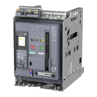
The trip units are designed for integration into circuit breakers, providing a user interface for configuration and status monitoring. The images show a display panel with buttons for "Test," "Configuration," and "Q" (likely for Quick access or specific function). The "OK" and "X" buttons suggest menu navigation and selection capabilities.

The functional test feature is a key usage aspect, allowing users to verify the correct operation of the trip unit without necessarily tripping the main circuit. This is crucial for routine maintenance and commissioning.

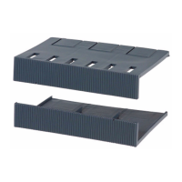
The device's design, as depicted in the removal and assembly diagrams, suggests a modular approach, allowing for easy installation, replacement, or upgrade of the trip unit within the circuit breaker assembly. The step-by-step instructions for removal and assembly, including the use of specific tools and torque values, highlight the precision required for proper integration.

Maintenance Features:

The manual strongly emphasizes safety during maintenance, with prominent warnings in multiple languages about hazardous voltage and the risk of death or serious injury. It explicitly states that all power sources must be turned off and locked out before any work is performed on the device. All covers must be replaced before re-energizing the device.

A critical maintenance feature is the requirement for qualified personnel to perform installation and maintenance tasks. This ensures that individuals with the necessary training and expertise handle the device, minimizing risks and ensuring proper operation.

The modular design facilitates maintenance by allowing the trip unit to be easily removed and reinstalled. The detailed diagrams for removal and assembly serve as a guide for technicians, ensuring that the process is followed correctly. The functional test procedures (TD310, TD410, TD420) are integral to maintenance, enabling technicians to verify the trip unit's health and performance after any service or during routine checks.

The provision of a technical support internet link (http://www.siemens.com/lowvoltage/technical-support) is a valuable maintenance feature, offering access to additional resources, troubleshooting guides, and expert assistance. The manual also states that it is subject to change without prior notice and should be stored for later use, indicating the importance of keeping up-to-date documentation for maintenance purposes.

Siemens 3VW9011-5AA00 Specifications

General IconGeneral
BrandSiemens
Model3VW9011-5AA00
CategoryIndustrial Equipment
LanguageEnglish

Related product manuals