36
Siemens · 10/2014
General data
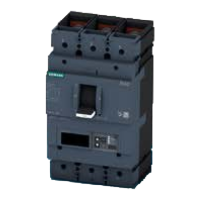
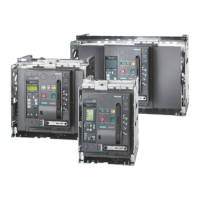
3WL Air Circuit Breakers
3WL air circuit breakers/non-automatic air circuit breakers up to 6300 A (AC), IEC
Protection functions ETU45B ETU76B
Parameterization by D& S M/K
Function overview of the electronic trip system
Overload protection
Function can be switched on/off
✓
--
✓
✓
Setting range
I
R
=
I
n
× ... 0.4-0.45-0.5-0.55-0.6-
0.65-0.7-0.8-0.9-1
0.4 ... 1
Switchable overload protection
(
I
2
t- or
I
4
t-dependent function)
✓ ✓
Setting range for time-lag class t
R
at
I
2
t 2-3.5-5.5-8-10-14-17-21-25-30 s 2 ... 30 s
Setting range for time-lag class t
R
at
I
4
t 1-2-3-4-5 s 1 ... 5 s
Thermal image can be switched on/off ✓ ✓
Phase failure sensitivity At t
sd
= 20 ms (M) ✓ (on/off)
N-conductor protection ✓✓
Function can be switched on/off ✓ ✓
N conductor setting range
I
N
=
I
n
× ... 0.5 ... 1 0.2 ... 2
Short-time delayed short-circuit protection ✓✓
Function can be switched on/off ✓ ✓
Setting range
I
sd
=
I
n
× ... 1.25-1.5-2-2.5-3-4-6-8-10-12 1.25
×
I
n
... 0.8 × I
cw
Setting range for delay time
t
sd
M-100-200-300-400 ms M-80 ... 4000 ms
Switchable short-time delayed short-circuit protection
(
I
2
t-dependent function)
✓ ✓
Setting range for delay time t
sd
at
I
2
t 100-200-300-400 ms 100 ... 400 ms
ZSI function By CubicleBUS module By CubicleBUS module
Instantaneous short-circuit protection ✓✓
Function can be switched on/off ✓ ✓
Setting range
I
i
=
I
n
× ... 1.5-2.2-3-4-6-8-10-12-0.8 x I
cs
1.5 ×
I
n
... 0.8 ×
I
cs
Ground-fault protection ❑ Module can be retrofitted ❑ Module can be retrofitted
Tripping and alarm functions ✓✓
Tripping function can be switched on/off ✓ ✓
Alarm function can be switched on/off -- ✓
Detection of the ground-fault current through summation
current formation with int. or ext. N conductor transf.
✓ ✓
Detection of ground-fault current through external
current transformer
✓✓
Setting range of the operating current
I
g
for tripping A-B-C-D-E A ... E
Setting range of the operating current
I
g
for alarm A-B-C-D-E A ... E
Setting range of the delay time t
g
100-200-300-400-500 ms 100 ... 500 ms
Switchable ground-fault protection characteristic curve
(
I
2
t-dependent function)
✓✓
Setting range for delay time t
g
at
I
2
t 100-200-300-400-500 ms 100 ... 500 ms
ZSI-G function By CubicleBUS module By CubicleBUS module
Parameter set changeover
Switchable between parameter set A and B -- ✓
LCD
Alphanumeric LCD (4-line) ❑ --
Graphical LCD (24 V, external power supply required) -- ✓
Communication
CubicleBUS integrated ✓ ✓
Communications capability via PROFIBUS DP ✓ ✓
Metering function
Metering function capability with metering function Plus ✓✓
LED display
Electronic trip unit active ✓ ✓
Alarm ✓ ✓
ETU fault ✓ ✓
L tripping operation ✓✓
S tripping operation ✓✓
I tripping operation ✓ ✓
N tripping operation ✓ ✓
G tripping operation ✓ (only with ground-fault prot. mod.) ✓ (only with ground-fault prot. mod.)
G alarm ✓ (only with ground-fault prot. mod.) ✓ (only with ground-fault prot. mod.)
Tripping operation as a result of ext. protect. functions ✓ ✓
Communication ✓ ✓
Signals from signaling switches with external CubicleBUS modules (relays)
Overload warning ✓✓
Load shedding, load absorbing ✓ ✓
Leading signal overload trip 200 ms ✓✓
Temperature alarm ✓ ✓
Phase unbalance ✓✓
Instantaneous short-circuit trip ✓ ✓
Short-time delayed short-circuit trip ✓✓
Overload trip ✓ ✓
Neutral conductor trip ✓✓
Ground-fault protection trip ✓ (only with ground-fault prot. mod.) ✓ (only with ground-fault prot. mod.)
Ground-fault alarm ✓ (only with ground-fault prot. mod.) ✓ (only with ground-fault prot. mod.)
Auxiliary relay ✓ ✓
ETU fault ✓✓
Setting range of the operating current I
g
Increment size when settings are made for the ETU76B using
the menu
Legend, see page 35.
Size I and size II Size III From ... to Increment size From ... to Increment size
A 100 A 400 A 0 ... 1 0.1 1000 ... 1600 50
B 300 A 600 A 1 ... 100 1 1600 ... 10000 100
C 600 A 800 A 100 ... 500 5 10000 ... max. 1000
D 900 A 1000 A 500 ... 1000 10
E 1200 A 1200 A
© Siemens AG 2015
 Loading...