38
Siemens · 10/2014
Project planning aids
3WL Air Circuit Breakers
3WL air circuit breakers/non-automatic air circuit breakers up to 6300 A (AC), IEC
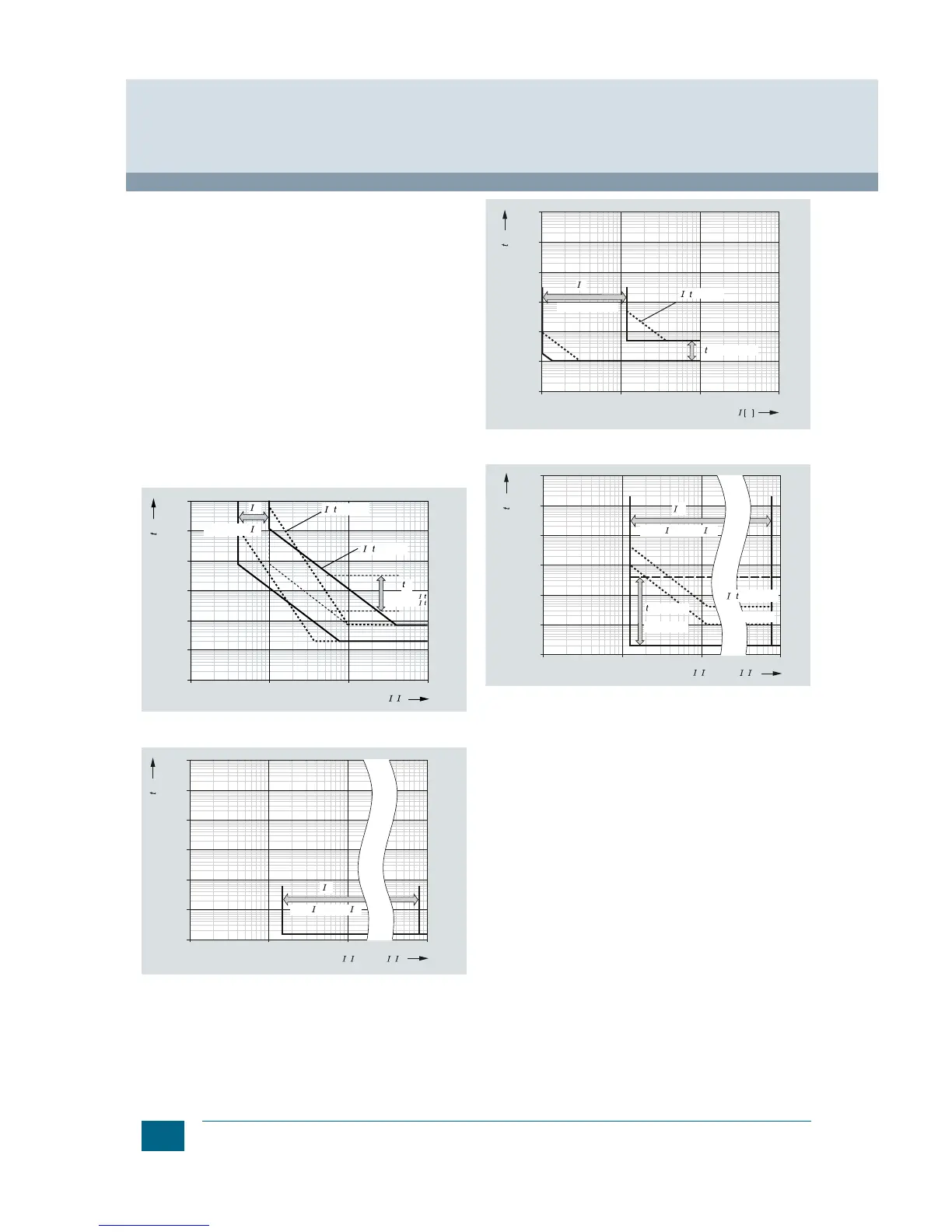
Every electronic trip unit type and every setting has its own
characteristic curve. Only a selection is shown in the following.
The characteristic curves each show the largest and smallest
setting range of 3WL circuit breakers with 1000 A rated current
at 500 V rated voltage with various trip units.
In order to obtain a complete tripping characteristic, the relevant
parts of the characteristics have to be combined.
The characteristic curves show the behavior of the electronic trip
unit when it is activated by a current that is already flowing
before the tripping operation. If the overcurrent tripping occurs
immediately after closing and the electronic trip unit is therefore
not yet activated, the opening time is extended, depending on
the level of the overcurrent by up to 15 ms. In order to determine
the total break-times of the circuit breakers, approximately 15 ms
must be added to the opening times shown for the arcing time.
Refer to the following legend for tolerances
.
The characteristic curves shown apply to ambient temperatures
at the circuit breaker between –5 and +55°C. The trip unit can be
operated at ambient temperatures of –20 to +70°C (ETU76B with
graphic display up to +55 °C). An extended tolerance band can
apply at these temperatures.
3WL circuit breaker with ETU45B and ETU76B electronic trip unit,
L characteristic curve
3WL circuit breaker with ETU45B and ETU76B electronic trip unit,
I characteristic curve
1)
Sizes I and II: 100 ... 1200 A
Size III: 400 ... 1200 A
3WL circuit breaker with ETU45B and ETU76B electronic trip unit,
G characteristic curve
3WL circuit breaker with ETU76B electronic trip unit,
S characteristic curve
Further characteristic curves are shown in the manual and
the planning and configuring tool SIMARIS design, or ask
your Siemens contact person.
Tolerances for the current settings
L: tripping operations between 1.05 and 1.2 × I
R
S: –0 %, +20 %
I: –0 %, +20 %
G: –0 %, +20 %
Tolerances for the tripping times
L: –20 %, +0 % for I
2
t characteristic curve
S: –0 %, +60 ms or -0 %, 10 % for tripping times greater than 600 ms
I: <50 ms
G: –0 %, +60 ms or -0 %, 10 % for tripping times greater than 600 ms
 Loading...