53
Siemens · 10/2014
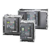
3WL Air Circuit Breakers
3WL non-automatic air circuit breakers up to 4000 A (DC)
General data
■
Technical specifications
1)
Make-time through activation solenoid for synchronization purposes
(short-time excited) 50 ms.
2)
Maintenance means: replace main contact elements and arc chutes
(see Operating Manual).
3)
Further technical specifications on request.
1)
At U
e
= 220 V DC.
2)
At U
e
= 300 V DC.
3)
At U
e
= 600 V DC.
4)
At U
e
= 1000 V DC.
Size I II
Type
3WL11 20
3WL12 10 3WL12 20 3WL12 40
Rated current I
n
at 40 °C
Main conductor A
2000
... 1000 2000 4000
Rated operational voltage U
e
(1000 V version, see Catalog LV 10, order code "A05")
V DC
1000 ... 600/1000 ... 600/1000 ... 600/1000
Rated insulation voltage U
i
V DC 1000 1000 1000 1000
Rated impulse withstand voltage U
imp
• Main conducting paths
• Auxiliary circuits
• Control circuits
kV
kV
kV
12
4
2.5
12
4
2.5
12
4
2.5
12
4
2.5
Isolating function acc. to EN 60947-2 Yes Yes Yes Yes
Utilization category B
Permissible ambient temperature
•Operation
•Storage
C
C
–25/+70
–40/+70
–25/+70
–40/+70
–25/+70
–40/+70
–25/+70
–40/+70
Permissible load
At rear horizontal main con-
nections (Cu painted black)
Up to 40 C
Up to 55 C
Up to 60 C
Up to 70 C
A
A
A
A
2000
1910
1850
1710
1000
1000
1000
1000
2000
2000
2000
1950
4000
3640
3500
3250
Power loss at I
n
for symmetrical loads
Withdrawable circuit breakers W
150 280 770 1640
Switching times
• Make time
• Opening time
• Electrical make time (through activation solenoid)
1)
• Electrical opening time (through shunt release)
• Electrical opening time (instantaneous undervoltage release)
ms
ms
ms
ms
ms
35
38
100
73
73
35
34
100
73
73
35
34
100
73
73
35
34
100
73
73
Endurance
3)
• Mechanical (without maintenance) Operating cycles
• Mechanical (with maintenance)
2)
Operating cycles
• Electrical (without maintenance) Operating cycles
• 1000 V version Operating cycles
• Electrical (with maintenance)
2)
Operating cycles
10 000
15 000
1000
1000
2000
10000
15000
6000
1000
15000
10000
15000
6000
1000
15000
10000
15000
4000
1000
15000
Switching frequency
• 600 V version
• 1000 V version
1/h
1/h
--
20
60
20
60
20
60
20
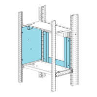
Mounting position
Degree of protection IP20 without cabinet door, IP41 with door sealing frame, IP55 with cover
Auxiliary conductors (Cu)
Max. number
Auxiliary conductors ×
cross-section
(solid/stranded)
Standard connection = strain-relief clamp
• Without end sleeve
• With end sleeve acc. to DIN 46228 Part 2
• With twin end sleeve
2 × 0.5 mm
2
(AWG 20) ... 2 × 1.5 mm
2
(AWG 16); 1 × 2.5 mm
2
(AWG 14)
1 × 0.5 mm
2
(AWG 20) ... 1 × 1.5 mm
2
(AWG 16)
2 × 0.5 mm
2
(AWG 20) ... 2 × 1.5 mm
2
(AWG 16)
Optional connection = tension spring
• Without end sleeve
• With end sleeve acc. to DIN 46228 Part 2
2 × 0.5 mm
2
(AWG 20) ... 2 × 2.5 mm
2
(AWG 14)
2 × 0.5 mm
2
(AWG 20) ... 2 × 1.5 mm
2
(AWG 16)
Weights 3-pole
4-pole
• Fixed-mounted circuit breakers
• Withdrawable circuit breakers
• Guide frames
• Fixed-mounted circuit breakers
• Withdrawable circuit breakers
• Guide frames
kg
kg
kg
kg
kg
kg
43
--
--
50
--
--
56
60
31
67
72
37
56
60
31
67
72
37
64
68
45
77
82
54
NSE0_00061a
30°
30°
 Loading...