58
Siemens · 10/2014
Project planning aids
3WL Air Circuit Breakers
3WL non-automatic air circuit breakers up to 4000 A (DC)
■
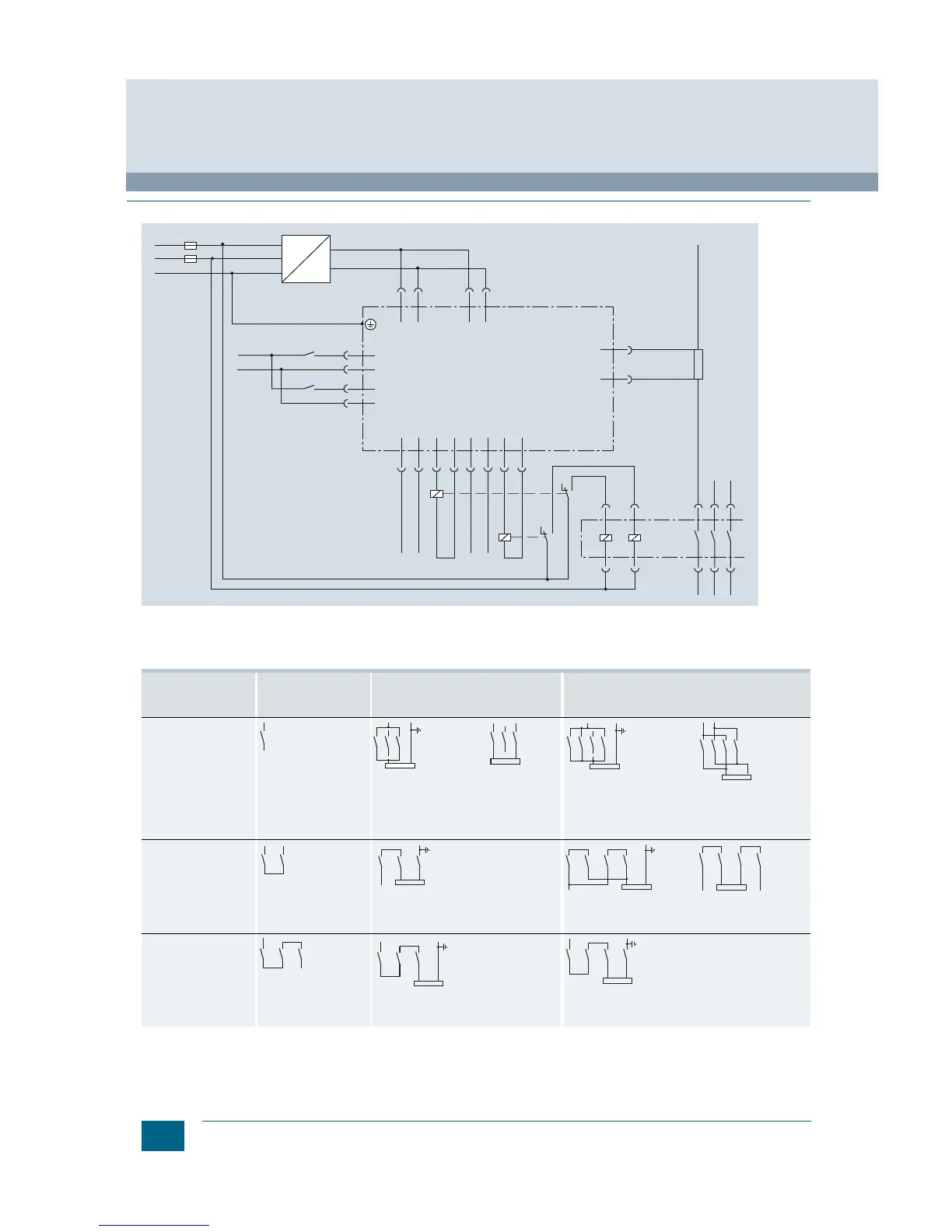
Circuit diagrams
Circuit diagrams of the DIGmat S100 and the 3WL non-automatic
air circuit breaker
Application examples
The connection to the circuit breakers is not dependent
on direction and polarity; the circuit diagrams can be adapted
accordingly.
If the parallel or series connections are made directly to the
connecting bars, for thermal reasons the continuous load on the
circuit breakers must only be 80 % of the permissible operational
current. If the parallel or series connection is made at a distance
of 1 m from the connecting bars, the circuit breaker can be used
at full operational current load.
]
Grounded system
Load
Rated operational
voltage
Required series-
connected contact gaps
at rated voltage
For 3-pole non-automatic air circuit
breakers
(operational currents up to 4000 A/
conducting path)
For 4-pole non-automatic air circuit breakers
(operational currents up to 4000 A/conducting path)
Up to 300 V + 10 %
1-pole,
2 parallel conducting
paths,
only with grounded
system
2-pole 1-pole,
3 parallel conducting paths,
only with grounded system
2-pole
2 parallel conducting
paths
Over 300 V + 10 %
Up to 600 V + 10 %
2-pole,
only with grounded
system
1-pole,
2 parallel conducting paths,
only with grounded system
2-pole
Over 600 V + 10 %
Up to 1000 V + 10 %
(version for 1000 V re-
quired, order with "-Z" and
order code A05)
1-pole,
only with grounded
system
2-pole,
only with grounded system
1-pole,
only with grounded
system