3
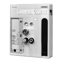
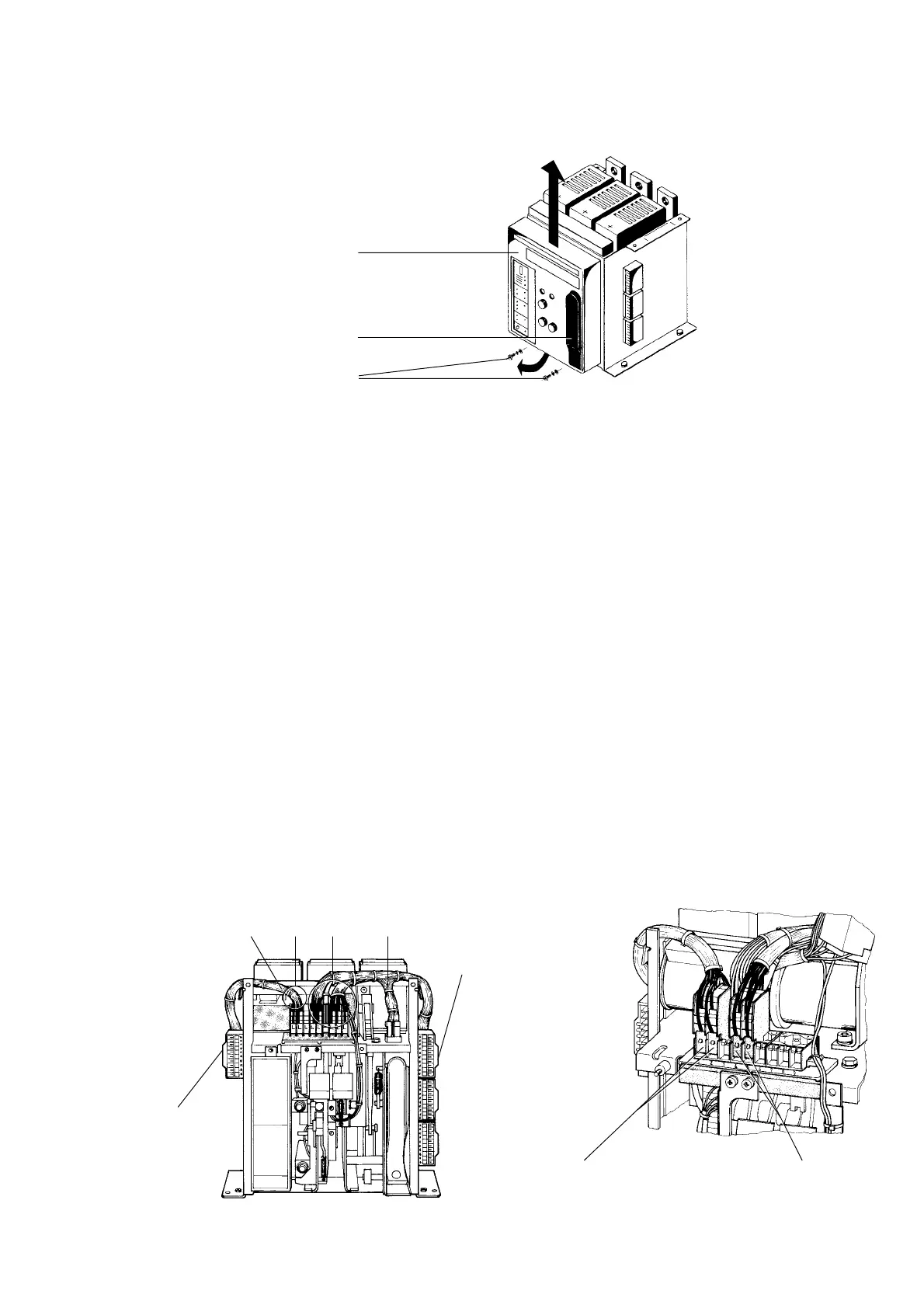
1.2 Removing the operating panel
- Undo fixing screws 5.2
- Pull operating handle 5.3 forwards
- Pull control panel 5.1 forwards at the bottom (a) and
remove upwards (b)
1.2 Bedienpult ausbauen
- Befestigungsschrauben 5.2 herausschrauben
- Handhebel 5.3 nach vorne klappen
- Bedienpult 5.1 unten vorklappen (a) und nach oben
abnehmen (b)
2 Mounting
2.1Installing 1st and/or 2nd auxiliary switch-block
(for circuit-breaker of size I - III, 3-pole and size I, II, 4-pole)
2 Montage
2.11. und/oder 2. Hilfsschalterblock einbauen
(für Leistungsschalter BG. I - III 3-pol. und BG. I, II 4-pol.)
Montieren des 1. Hilfsschalterblockes
- Anschlußelement -X1 auf Hutschiene aufrasten (Fig. 6a)
- Leitungen gemäß Fig. 6a bis zur Pos. Y führen
- Hilfsschalterblock von oben bis zum Verrasten auf den
Platz 4 und 5 des Hilfsschalterträgers aufschieben
(Fig. 6b)
Bei Leistungsschaltern ohne Bohrung im Motorquerträger
entfallen die folgenden Punkte:
- Kabelbinder am Leistungsstrang (3) lösen (Fig. 6a)
- Leitungen des Hilfsschalterblockes und Leitungsstranges (3)
mit mindestens 4 Kabelbindern abbinden und an Bohrungen
des Motorquerträgers mit Kabelbindern befestigen
Montieren des 2.Hilfsschalterblockes
- Anschlußelement -X4 auf der Hutschiene aufrasten (Fig. 6a)
- Leitungen gemäß Fig.6a bis zur Pos.X führen
- Hilfsschalterblock von oben bis zum Verrasten auf den
Platz 1 und 2 des Hilfsschalterträgers aufschieben (Fig. 6b)
Bei Leistungsschaltern ohne Bohrungen im Motorquerträger
entfällt der folgende Punkt:
- Leitungen an Bohrungen des Motorquerträgers (4) mit
Kabelbindern befestigen
Fitting the 1st auxiliary switch block
- Snap terminal -X1 onto the top-hat rail (Fig. 6a)
- Lead the wires up to position Y according to Fig. 6a
- Push the auxiliary switch block from above onto the
places 4 and 5 of the auxiliary switch bracket until it
latches into position (see Fig. 6b)
The following points do not apply for circuit-breakers without
drilled holes in the motor cross-arm:
- Loosen the cable binder at cable 3 (Fig. 6a)
- Bind wires of the auxiliary switch block and cable (3) with
at least four cable binders and fix with cable binders at
the drilled holes of the motor cross-arm
Fitting the 2nd auxiliary switch block
- Snap terminal -X4 onto the top-hat rail (Fig. 6a)
- Lead the wires up to position X according to Fig.6a
- Push the auxiliary switch block from above onto the places 1
and 2 of the auxiliary switch bracket until it latches into position
(see Fig. 6b)
The following points do not apply for circuit-breakers without
drilled holes in the motor cross-arm:
- Fix the wires with cable binders at the drilled holes of the
motor cross-arm
Fig. 6a Leitungen verlegen/
Laying the wires
1. Hilfsschalterblock
1st auxiliary switch block
2. Hilfsschalterblock
2nd auxiliary switch block
Fig. 6b Hilfsschalterblock montieren/
Installing the auxiliary switch block
4
X
Y 3
Anschlußelement -X4
Snap terminal -X4
Anschlußelement -X1
Snap terminal -X1
5.2
Fig. 5 Bedienpult ausbauen/
Removing the control panel
5.3
b
5.1
a
 Loading...