Do you have a question about the Siemens 3WN Series and is the answer not in the manual?
Warning about dangerous electrical voltage and securing against reclosing.
Only qualified personnel may perform installation and assembly work.
Details auxiliary switch block compatibility with different circuit-breaker sizes.
Lists the items included in the packing unit for auxiliary switch blocks.
Instructions for removing the door sealing frame, applicable to specific breaker models.
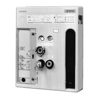
Step-by-step guide to removing the control panel from the circuit breaker.
Procedure for installing auxiliary switch blocks for specific circuit-breaker sizes.
Instructions for opening cable ducts and routing wires for older circuit-breaker models.
Procedure for installing auxiliary switch blocks for specific circuit-breaker sizes.
Instructions for updating nameplates with new data using an indelible pen or ordering new plates.
| Rated Voltage | Up to 690V AC |
|---|---|
| Standards | IEC 60947-2 |
| Rated Current | 630A to 6300A |
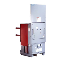
| Mounting Type | Fixed or Withdrawable |
| Protection Functions | Overload, Short-circuit, Ground fault |
| Poles | 3 or 4 |