6
Building Technologies A6V10200373_n_--_--
Fire Safety 2017-10-31
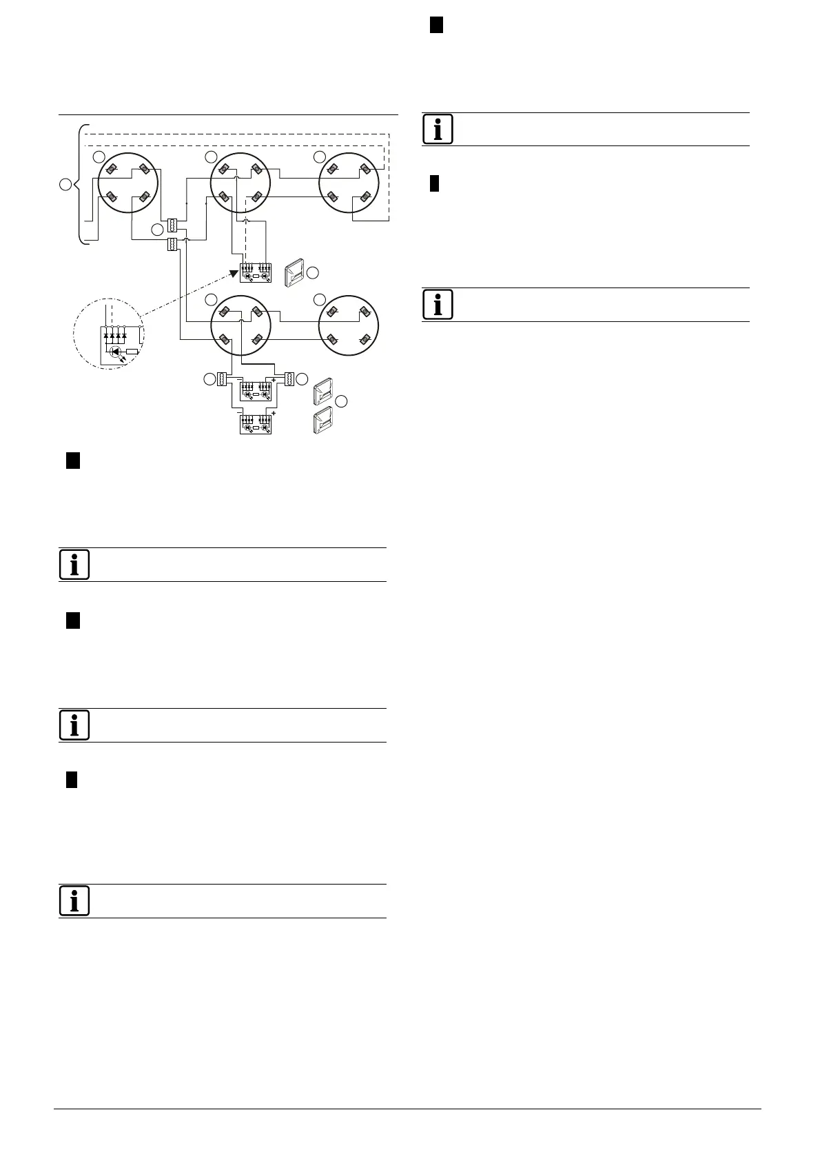
Connection diagram C-NET
Anschlussschema C-NET
Schéma de raccordement C-NET
Diagrama de conexión C-NET
Schema di collegamento C-NET
5 6
5 6
1a 1b
5 6
1a 1b
5 6
5 6
+
–
+
–
2
1
3
+
–
3
22
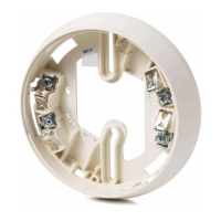
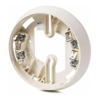
Detector base DB72x, sounder base DBS720
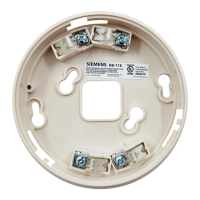
Auxiliary terminal DBZ1190
more information, refer to document
A6V10212047.
Meldersockel DB72x, Signalsockel DBS720
Weitere Informationen siehe
Dokument A6V10212047.
Equipement de contrôle et de signalisation
Embase de détecteur DB72x, embase sonore
DBS720
Terminal auxiliaire DBZ1190
Indicateur d'action externe
Pour obtenir davantage d'informations, voir
document A6V10212047.
Zócalo del detector DB72x, zócalo con sirena
DBS720
Terminal de auxiliar DBZ1190
Indicador de alarma externo
Para más información, consulte el documento
A6V10212047.
Base del rivelatore DB72x, base con cicalino
integrato DBS720
Morsetto ausiliario DBZ1190
Indicatore esterno di allarme
Per ulteriori informazioni, vedere il documento
A6V10212047.