Figure 3 Wiring Diagram for DB-11/-11E using HFP-11 and HFPT-11 Detectors
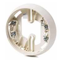
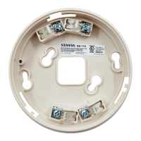
Model DB-11/-11E
(P/N 500-094151/500-094151E)
Siemens Building Technologies, Inc.
8 Fernwood Road
Florham Park, New Jersey 07932
Siemens Building Technologies, Ltd.
2 Kenview Boulevard
Brampton, Ontario, Canada L6T 5E4
Figure 2 Wiring Diagram for DB-11/-11E using FP-11, FPT-11, FS-DP, FS-DPT, and FS-DT Detectors
1a6
-
--
----
+
+++ +++
TO INITIATING
CIRCUIT OF
SBT, INC.
COMPATIBLE
CONTROL UNIT
OPTIONAL
REMOTE
ALARM
INDICATOR
MODELS
RLI-1 / RLI-2
TO NEXT BASE
TO NEXT BASE
DO NOT
USE AN
END OF
LINE
DEVICE
DB-11/-11E (NO REMOTE DEVICE)
5
6
1a
1b
5
6
1a
1b
RELAY*
CONTACTS
3A, 120 VAC
3A, 30 VDC
DB-11XRS (REMOTE RELAY BASE)
*The relay contacts are shown in the Non-Alarm/System Reset condition.
5+
NO
C
NC
6–
5+
NO
C
NC
6–
DO NOT
USE AN
END OF
LINE
DEVICE
TO INITIATING
CIRCUIT OF
SBT, INC.
COMPATIBLE
CONTROL UNIT
OPTIONAL
REMOTE
ALARM
INDICATOR
MODELS
RL-HW / RL-HC
TO NEXT BASE
TO NEXT BASE
DO NOT
USE AN
END OF
LINE
DEVICE
DB-11/-11E (NO REMOTE DEVICE)
LINE 1**
LINE 2**
TB1
TB3
TB2
5
6
1a
1b
5
6
1a
1b
RELAY*
CONTACTS
3A, 120 VAC
3A, 30 VDC
DB-HR (REMOTE RELAY BASE)
*The relay contacts are shown in the Non-Alarm/System Reset condition.
**HFP-11/HFPT-11 is a polarity insensitive detector. Line 1 and Line 2 can be either line of the loop.
5+
NO
C
NC
6–
5+
NO
C
NC
6–
DO NOT
USE AN
END OF
LINE
DEVICE
Figure 1 Wiring Diagram for DB-11/-11E using PE-11, PE-11T, and DT-11 Detectors
CAUTION:
1. Do not use looped wire under base terminal 5. Break wire
run to provide supervision of connection.
2. When a remote relay is used to control a critical system
function, the relay and its associated detector and optional
module(s) must be the ONLY devices on the initiating circuit.
Installation/Wiring Instructions
MODEL DB-11/-11E DETECTOR BASE
Fire Safety
1b
6
5
END OF LINE DEVICE
(NOTE POLARITY
WHEN APPLICABLE)
1a
1b
1b
5
5
6
+
-
+
-
(SEE CAUTION 1)
MULTIPLE REMOTE DEVICES
If remote devices are supported by the initiating circuit, each detector/base may
have up to 2 remote devices with the following configurations and restrictions only:
Remote
Device 1
RR-11
RR-11
RLC-11, RLW-11
RLC-11, RLW-11
Remote
Device 2
RLC-11, RLW-11
RSAC-11, RSAW-11
RSAC-11, RSAW-11
RLC-11, RLW-11
Restrictions
See Caution 2
See Caution 2
Wire from base to
RSAC-11/RSAW-11 to RL-11
SEE REMOTE DEVICE INSTRUCTIONS FOR WIRING DETAILS:
DEVICE
RR-11
RLC-11, RLW-11
RSAC-11, RSAW-11
INSTALLATION
INSTRUCTIONS
P/N 315-094924
P/N 315-094925
P/N 315-094926
TO INITIATING
CIRCUIT OF
SBT, INC.
COMPATIBLE
CONTROL UNIT
DB-11/-11E (NO REMOTE DEVICE)
DB-HR (REMOTE RELAY BASE)