GB
L1V30049867A DS02 1 / 4
s
Gamma instabus
Präsenzmelder, Konstantlichtregler UP 258E22
Presence Detector, Constant Controller UP 258E22
5WG1 258-2EB22
Präsenzmelder, Helligkeitssensor UP 258D12
Presence Detector, Brightness Sensor UP 258D12
5WG1 258-2DB12
Bedien- und Montageanleitung
Operating and Mounting Instructions
Stand: Dezember 2014
Issued: December 2014
Bild 1 / figure 1
Bild 2 / figure 2
Bild 3 / figure 3
Produkt- und Funktionsbeschreibung
Das Gerät ist ein Präsenz-, Bewegungsmelder mit integrierter
Helligkeitserfassung. Das Gerät kommuniziert über KNX. Es ist
zur Montage an die Decke konzipiert.
Die beiden Geräte unterscheiden sich im Funktionsumfang und
in der Inbetriebnahme:
UP 258E22 UP 258D12
Inbetriebnahme mit ETS ETS
Konstantlichtregler ja no
2-Punktlichtregler ja ja
Inbetriebnahme / Auslieferzustand
Nach Anschluss des Gerätes an Busspannung muss der Melder
zuerst „Anlaufen“, d.h. der Bewegungssensor wird bis zu 40 s
initialisiert.
Auslieferzustand
Im Auslieferzustand ist der Parameter Betriebsart auf Einstell-
modus eingestellt.
Während sich das Gerät im „Einstellmodus“ befindet, zeigt die
eingebaute Programmier - LED den Zustand des PIR-Sensors an.
(leuchtet bei Bewegung kurz auf).
Der Programmiermodus kann im Auslieferzustand auch mit der
als Zubehör erhältlichen IR-Fernbedienung S 255/11
5WG1 255-7AB11 (S3 = On / S4 = Off) aktiviert bzw. deaktiviert
werden.
Programmiermodus
Durch kurzes Drücken der Programmiertaste (< 2 s) wird der
Programmiermodus aktiviert. Dies wird durch Dauerleuchten der
Programmier-LED angezeigt. Durch erneutes Drücken wird der
Programmiermodus deaktiviert.
Nur UP 258D12 Werkseinstellung
Durch sehr langes Drücken der Programmiertaste (> 20 s) wird
das Gerät auf die Werkseinstellung zurückgesetzt. Dies wird
durch gleichmäßiges Blinken der Programmier-LED mit Dauer
8 s angezeigt.
Nur UP 258D12 Hinweis
Durch längeres Drücken der Programmiertaste (> 5 s und < 20 s)
wird der Verbindungstest für die Inbetriebnahme mit Desigo
gewählt. Dieser Modus kann durch kurzes Drücken beendet
werden.
Verhalten nach Programmierung
Das Verhalten des Gerätes nach Programmierung mit der ETS ist
abhängig von der Parametrierung. Die Beschreibung der Funkti-
onalitäten, Parameter und der Objekte befindet sich in der App-
likationsprogrammbeschreibung (APB) des Gerätes.
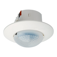
Lage- und Funktion der Anzeige- und Bedienelemente
(siehe Bild 1)
A1 Gerät
A2 Haltefedern
A3 Erfassungslinse
A4 Programmiertaste
A5 Abschattung
A6 Busklemme
A7 Designring
A8 Programmier-LED unter Linse
Montage und Verdrahtung
Υ
GEFAHR
· Das Gerät darf nur von einer zugelassenen Elektrofachkraft
installiert und in Betrieb genommen werden.
· Bei Anschluss des Gerätes ist darauf zu achten, dass das Ge-
rät freigeschaltet werden kann.
· Das Gerät darf nicht geöffnet werden.
· Bei der Planung und Errichtung von elektrischen Anlage n
sind die einschlägigen Richtlinien, Vorschriften und Bestim-
mungen des jeweiligen Landes zu beachten.
Das Gerät ist für Deckenmontage vorgesehen.
Empfohlene Montagehöhe: 2,4m – 3,0m
Hierbei gibt es die folgenden Möglichkeiten der Montage:
(siehe Bild 2):
à UP Montage (A) in einer UP – Dose mittels
Schraubbefestigung
à UP Montage (A) mit Haltefedern in der
Zwischendecke.
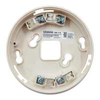
à AP Montage (B) im AP- Gehäuse (siehe Zubehör)
Anschluss des Melders
(siehe Bild 3)
D1 Gerät
D2 Busklemme
D2.1 (-) Klemme (grau)
D2.2 (+) Klemme (rot)
D2.3 Prüfkontakt
D2.4 Ader der Busleitung
Anklemmen:
Adern in Busklemme einstecken. Abisolierlänge beachten!
Busklemme auf Stecker im Gerät aufstecken (siehe Bild3)
Abklemmen:
Busklemme vom Gerät lösen (evtl. mittels Schraubendreher)
Adern mittels Drehen von der Busklemme lösen.
Product and Applications Description
The device is a presence and motion detector with integrated
brightness sensor. The device communicates via KNX. It is de-
signed for ceiling mounting. The devices differ in commission-
ing and functionality:
UP 258E22 UP 258D12
Commissioning with ETS ETS
Constant light level
controller
yes no
2-point light controller yes yes
Commissioning / Factory default
After the device is connected to the bus voltage, the sensor
must first "Restart", i.e. the motion sensor will be initialized.
Factory default
In the delivered state, the parameter Operating Mode is set to
setting mode.
While the device is in "Setting Mode", the integrated program-
ming LED displays the PIR sensor state. (flashes briefly with mo-
tion).
The progamming mode can be set in factory default status also
with the available IR remote control S 255/11 5WG12557AB11
(S3 = On / S4 = Off).
Programming mode
A short push of learning button (< 2 s) enables the program-
ming mode. This will be indicated by a continuous light at the
programming mode LED. A second push disables this mode.
Only UP258D12: factory settings
A very long push of the learning button (> 20 s) effects a reset
to factory settings. This is indicated by constant flashing for 8
seconds.
Only UP258D12: note
A long push of the learning button (> 5 s and <20 s ) enabled
the Connection Test for commissioning with Desigo. This mode
can be disabled by a short push any time.
Behavior after programming
The behavior of the device after programming with the ETS is
dependent on the configuration. The description of the features,
parameters and objects is in the application program description
(APB) of the device.
Location / Function of the Display and Operating Elements
(see figure 1)
A1 Device
A2 Fixing clamps
A3 Detector lens
A4 Learning button
A5 Shade
A6 Bus terminal
A7 Design ring
A8 Programming mode LED behind lens
Mounting and Connecting
Υ
DANGER
· The device must be mounted and commissioned by an au-
thorized electrician.
· When connecting the device, it should be ensured that the
device can be isolated.
· The device must not be opened.
· For planning and construction of electric installations, the
relevant guidelines, regulations and standards of the respec-
tive country are to be considered.
The device is intended for ceiling mounting.
Recommended mounting height: 2.4m – 3.0m
There are the following options for this:
(see figure 2):
à UP mounting (A) in an UP socket with screw fixing
à UP mounting (A) with fixing claws in suspended ceiling
à AP mounting (B) in the AP housing (see accessories)
Connecting the detector
(see figure 3)
D1 Device
D2 Bus terminal
D2.1 (-) Terminal (grey)
D2.2 (+) Terminal (red)
D2.3 Test contact
D2.4 Bus line wire
Connecting:
Plug wires into the bus terminal. Ensure you have stripped the
insulation back!
Push the bus terminal on the plug in the device (see figure 3)
Disconnecting:
Separate the bus terminal from the device (use a screwdriver if
necessary) Separate the wires from the bus terminal by turning.
A1
A2
A3
A6
A4
A5
A7
A8