EasyManua.ls Logo

Siemens LAE10 User Manual

Siemens LAE10
15 pages
To Next Page IconTo Next Page
Page #1 background imageLoading...
Page #1 background image
44 ซ.บรมราชชนนี 70 ถ.บรมราชชนนี ศาลาธรรมสพน์ ทวีวฒนา กทม. 10170.
website: https://www.add-furnace.com/ โทร: 02-888-3472
Line ID: @add11 Wechat ID: add0883001122
7781
Flame Safeguards LAE10
LFE10
Flame safeguards for burners with intermittent operation
The LAE10 is used for the supervision and indication of oil flames
The LFE10 is used for the supervision and indication of gas and oil flames
Supplementary Data Sheets for flame detectors, refer to N7712 and N7713
For control units LEC1 for continuous operation, refer to Data Sheet N7761
The LAE10 / LFE10 and this Data Sheet are intended for use by OEMs which
integrate the flame safeguards in their products!
Use
Flame safeguards for oil burners and oil units with or without a fan in
accordance with DIN EN 60730-2-5:2005 and DIN EN 230:2005
Flame safeguards for gas burners and gas-fired appliances with or without a fan in
accordance with DIN EN 60730-2-5:2005 and DIN EN 298:2004
Note!
Donot use for new designs.
LAE10 For the supervision of oil flames
Flame supervision with silicon photocell detector RAR9
LFE10 For supervision of gas flames and luminous or blue-burning oil flames
Flame supervision with flame detector QRA or ionization probe
CC1N7781en
01.08.2016
Building Technologies Division

Other manuals for Siemens LAE10

Question and Answer IconNeed help?

Do you have a question about the Siemens LAE10 and is the answer not in the manual?

Siemens LAE10 Specifications

General IconGeneral
BrandSiemens
ModelLAE10
CategorySecurity Sensors
LanguageEnglish

Summary

Flame Safeguards LAE10/LFE10 Usage

LAE10 Oil Flame Applications

Supervision and indication of oil flames, for oil burners with/without fan.

LFE10 Gas/Oil Flame Applications

Supervision of gas/oil flames, for gas burners with/without fan.

Important Design Note

Intended for OEMs; advises against use for new designs.

General Information and Applications

Applications with LEC1 Control Units

Use with LEC1 for dual-supervision, forced draft, multiflame, and manual startup.

Other Burner Control Compatibility

Compatibility with other burner controls and manual startup combustion plants.

Safety Precautions and Warnings

General Safety Guidelines

Guidelines to prevent injury, property damage, and environmental harm.

Specific Hazard Alerts

Warnings on tampering, electrical shock, impact damage, and UV radiation.

Engineering and Installation Notes

Engineering Notes: Relay Timing

Ensure drop out delay time of relay «d» does not exceed 50 ms.

Mounting and Installation

Comply with regulations; mount on burner/panels; run ignition cables separately.

Electrical Connection of Detectors

Ensure disturbance-free signal transmission; use separate cables and observe lengths.

Standards, Certificates, and Lifecycle

Compliance with Standards

Adherence to CE directives and standards for gas/oil burner controls.

Designed Product Lifetime

Designed lifetime of 250,000 startup cycles or approx. 10 years.

Product Details and Features

Disposal and Mechanical Design

Dispose of electronic components properly; unit has plug-in design with impact-proof housing.

Special Features

LAE10: light simulation test; LFE10: UV tube voltage increase test.

Flame Supervision Methods

Supervision using UV detectors (QRA/QRA10/QRA4) or ionization probe.

Type Summary and Ordering

Overview of flame safeguards and ordering information for LAE10/LFE10.

Accessories

Flame Detectors

Available flame detectors include UV types (QRA2, QRA10, QRA4) and silicon photocell (RAR9).

Plug-in Bases

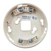
Details on low and high plug-in bases with 10-pole screw terminals and cable entries.

Technical Data

General Unit Data

Specifications including mains voltage, frequency, power consumption, and contact rating.

Weight Specifications

Weight details for LAE10 and LFE10 with and without plug-in bases.

Flame Supervision Current

Required and possible detector current for RAR9, ionization probe, and QRA.

Connecting Cable Lengths

Permissible length of connecting cables, with notes on low-capacitance cables.

Environmental and Measurement Data

Environmental Conditions

Climatic and mechanical conditions for storage, transport, and operation.

Measuring Circuits

Diagrams for ionization probe, QRA, and RAR9 measuring circuits with legend.

Functionality and Operation Modes

Basic Function with LEC1

How flame safeguards feed signals to LEC1, including shutdown and lockout logic.

Flame Simulation and Detector Tests

Tests performed by LEC1 for LAE10/LFE10 and conditions causing lockout.

Ionization Probe Operation

Note on terminal 6 connection for ionization probes as no detector test is needed.

Operational Modes and Diagrams

Dual-Supervision Operation

Detailed connection diagram for dual-supervision of oil burners.

Dual-Supervision Logic

Supervision by two safeguards; loss of signal from either causes lockout.

Multi-Burner Operation Modes

Supervision of 2 Manually Controlled Burners

Operation mode and logic for supervising two burners, including start and shutdown.

UV Radiation Warning

Cautionary note on UV tube as a radiation source and placement of detectors.

Multi-Flame Supervision Details

Multi-Flame Supervision for Gas Burners

Connection diagram and logic for multi-flame supervision of gas burners.

Lockout Conditions

Conditions causing burner lockout in multi-flame supervision, including flame establishment.

Restart Procedures

Procedures for restarting burners after a fault or shutdown in multi-flame systems.

Basic Circuit Diagrams

LFE10 with QRA Detector Circuit

Circuit diagram for LFE10 using QRA flame detector, with earth connection note.

LFE10 with Ionization Supervision Circuit

Circuit diagram for LFE10 using ionization probe, with earth connection note.

LAE10 with RAR9 Circuit

Circuit diagram for LAE10 using RAR9 silicon photocell detector.

Dimensions and Base Versions

Low Plug-in Base Dimensions

Detailed dimensions and design features of the low plug-in base.

High Plug-in Base Dimensions

Detailed dimensions and design features of the high plug-in base.

Related product manuals