EasyManua.ls Logo

Siemens QRI2B2.B180B1

Siemens QRI2B2.B180B1
12 pages
To Next Page IconTo Next Page
Loading...
CC1N7719en
17.07.2018
Building Technologies
7
719
Infrared Flame Detectors
QRI...
Infrared flame detectors for use with Siemens burner controls, for the
supervision of gas, oil and other flames that emit infrared light.
The QRI... are suited for burners of any capacity, either in continuous or
intermittent operation.
The QRI... and this Data Sheet are intended for use by OEMs which integrate the
flame detectors in their products.
Use, features
Key features of the QRI... flame detectors:
- Detector with infrared-sensitive flame detecting element
- Integrated flame signal amplifier
- Designed for frontal and lateral (90°) illumination
- Suited for use with burner controls type LMV5...
- Secured to the burner with flange and clamp
The spectral sensitivity of the QRI... is a maximum of about 2 µm covering infrared
radiation emitted by gas, oil, and coal flames as well as other sources of infrared light.
Owing to electronic self-supervision of the flame signal, the QRI... can be used in
connection with suitable burner controls designed for burners in continuous or
intermittent operation.
The sensitivity of the QRI... is such that it must be fitted behind the burner’s baffle plate.
Question and Answer IconNeed help?

Do you have a question about the Siemens QRI2B2.B180B1 and is the answer not in the manual?

Siemens QRI2B2.B180B1 Specifications

General IconGeneral
TypeFlame Detector
Flame SensorYes
Supply Voltage24 V DC
Frequency50/60 Hz
Current Consumption≤ 100 mA
Operating Temperature-20°C to +60°C
Weight500 grams

Summary

Use and Features of Infrared Flame Detectors

Warning Notes and Mounting Instructions

Critical Safety Precautions

Critical safety precautions to prevent injury, damage, or environmental harm.

Flame Detector Mounting Guidelines

Guidelines for the correct and safe installation of the flame detector.

Installation and Commissioning Procedures

Proper Installation Positioning

Instructions for proper positioning and viewing range setup of the flame detector.

Electrical Connection Best Practices

Recommendations for achieving reliable signal transmission through proper wiring.

Commissioning Safety Checks

Procedure for safety checks during plant commissioning and maintenance.

Compliance, Service, and Design

Standards and Certification Marks

Information on compliance marks, quality standards, and hazardous substances.

Detector Lens Cleaning Service

Instructions for cleaning the detector's lens.

Environmentally Sound Disposal

Guidelines for the environmentally sound disposal of the flame detector.

Mechanical Housing and Mounting

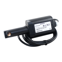
Description of the detector's housing, lens fitting, and mounting mechanism.

Available Detector Model Summary

Overview of available article numbers, type references, illumination types, and cable configurations.

Optional Accessories for Installation

Technical Detector Specifications

General Detector Data Sheet

Specifications for operating voltage, signal voltage, cable length, degree of protection, power consumption, and safety class.

Environmental Operating Conditions

Details on climatic conditions, temperature range, and humidity for storage, transport, and operation.

Detector Functional Principles

Maximum Connecting Cable Length

Information on the maximum permissible length of the detector connecting cable.

Flame Spectral Emission and Sensitivity

Measurement and Connection Examples

Measuring Detector Signal

Guidance on measuring detector current and signal voltage with a voltmeter.

Mounting Kit Component Diagram

Diagram showing the mounting kit components and their arrangement.

Detector Dimensional Drawings

Lateral Illumination Model Dimensions

Dimensional drawings and viewing angle for lateral illumination models.

Frontal Illumination Model Dimensions

Dimensional drawings and viewing angle for frontal illumination models.

Continued Detector Dimensions and Kits

Connecting Cable Stripping Details

Diagram showing the connecting cable stripping and wire colors.

AGG2.110 Mounting Kit Dimensions

Dimensions and components of the AGG2.110 mounting kit.

AGG2.120 Adapter Dimensions

Dimensions and specifications of the AGG2.120 adapter.

Further Dimension Details for Accessories

AGG04 Mounting Coupling Dimensions

Dimensions and features of the AGG04 mounting coupling.

Straight Flange 4 241 8898 0 Dimensions

Dimensional drawing of the straight flange accessory.

Flange with Radius 4 241 88550 Dimensions

Dimensional drawing of the flange with radius accessory.

Related product manuals